Table of Contents
Advertisement
Preface..................................................................................................................................... III
1. Basic safety information................................................................................................... - 1 -
1.1. Safety instructions...............................................................................................- 1 -
1.2. Symbols and signs...............................................................................................- 4 -
2. Product characteristics...................................................................................................... - 6 -
2.1. Product dimensions............................................................................................. - 6 -
2.2. Function description............................................................................................- 8 -
2.3. Efficiency curve................................................................................................ - 10 -
3. Installation...................................................................................................................... - 11 -
3.1. Installation Process............................................................................................- 11 -
3.2. Checking Before Installation............................................................................ - 12 -
3.3. Tools..................................................................................................................- 14 -
3.4. Determining the Installation Position............................................................... - 15 -
3.5. Moving the SOFAR 3K~6KTLM-G2...............................................................- 17 -
3.6. Installing SOFAR 3K~6KTLM-G2.................................................................. - 18 -
4. Electrical Connections.................................................................................................... - 20 -
4.1. Electrical connection.........................................................................................- 21 -
4.2. Connecting PGND Cables................................................................................ - 21 -
4.3. Connecting DC Input Power Cables................................................................. - 23 -
4.4. Connecting AC Output Power Cables...............................................................- 26 -
4.5. RS485,CT,inverter logic interface connection.................................................. - 29 -
4.6. WIFI/GPRS module installation procedure...................................................... - 34 -
4.7. Communication method....................................................................................- 35 -
5. Commissioning of inverter............................................................................................. - 39 -
5.1. Safety inspection before commissioning.......................................................... - 39 -
5.2. Start inverter......................................................................................................- 39 -
6. Operation interface......................................................................................................... - 40 -
6.1. Operation and Display Panel.............................................................................- 40 -
6.2. Standard Interface............................................................................................. - 41 -
6.3. Main Interface................................................................................................... - 44 -
6.4. Update Software online.....................................................................................- 48 -
7. Trouble shooting and maintenance................................................................................. - 50 -
7.1. Trouble shooting............................................................................................... - 50 -
7.2. Maintenance...................................................................................................... - 55 -
8. Technical data................................................................................................................. - 57 -
8.1. Input parameters (DC)...................................................................................... - 57 -
8.2. Output parameters (AC)....................................................................................- 58 -
8.3. Efficiency,Protection and Communication....................................................... - 59 -
8.4. General Date..................................................................................................... - 60 -
9. Quality Assurance...........................................................................................................- 61 -
SOFAR 3K~6KTLM-G2
Contents
Copyright © Shenzhen SOFARSOLAR Co., Ltd
I
User manual
Advertisement
Table of Contents

Related Manuals for Sofar solar 3K~6KTLM-G2


Summary of Contents for Sofar solar 3K~6KTLM-G2
-
Page 1: Table Of Contents
3.2. Checking Before Installation................- 12 - 3.3. Tools........................- 14 - 3.4. Determining the Installation Position............... - 15 - 3.5. Moving the SOFAR 3K~6KTLM-G2...............- 17 - 3.6. Installing SOFAR 3K~6KTLM-G2..............- 18 - 4. Electrical Connections....................- 20 - 4.1. Electrical connection..................- 21 - 4.2. - Page 2 User manual SOFAR 3K~6KTLM-G2 Notice This manual contains important safety instructions that must be followed during installation and maintenance of the equipment. Save these instructions! This manual must be considered as an integral part of the equipment. The manual must always accompany the equipment,even when it is transferred to another user or field.
-
Page 3: Preface
Please read the product manual carefully before installation,operation or maintenance.This manual contains important safety instructions and installation instructions that must be followed during installation and maintenance of the equipment. Scope This product manual describes the installation,electrical connections, commissioning,maintenance and troubleshooting of SOFAR 3K~6KTLM-G2 inverters: 3KTLM-G2 3.6KTLM-G2 4KTLM-G2 4.6KTLM-G2... - Page 4 User manual SOFAR 3K~6KTLM-G2 Danger indicates a hazardous situation which, if not avoided, will result in death or serious injury. Danger Warning indicates a hazardous situation which, if not avoided, could result in death or serious injury. Warning Caution indicates a hazardous situation which, if not avoided, could result in minor or moderate injury.
-
Page 5: Basic Safety Information
User manual SOFAR 3K~6KTLM-G2 1. Basic safety information If you have any question or problem when you read the following information, please contact Shenzhen SOFARSOLAR Co., Ltd. Note Outlines of this chapter Safety instruction It mainly introduce the safety instruction when install and operate the equipment. - Page 6 User manual SOFAR 3K~6KTLM-G2 Qualified persons The customer must make sure the operator has the necessary skill and training to do his/her job.Staff in charge of using and maintaining the equipment must be skilled,aware and mature for the described tasks and must have the reliability to correctly interpret what is described in the manual.
- Page 7 User manual SOFAR 3K~6KTLM-G2 SOFARSOLAR Co.Ltd for help if necessary. Transport of the equipment, especially by road, must be carried out with by suitable ways and means for protecting the components (in particular, the electronic components) from violent shocks, humidity, vibration, etc.
-
Page 8: Symbols And Signs
User manual SOFAR 3K~6KTLM-G2 Before any repair work, turn OFF the AC circuit breaker between the inverter and electrical grid first, then turn OFF the DC switch. After turning OFF the AC circuit breaker and DC switch, wait for 5 minutes at least before carrying out any maintenance or repair Danger work. - Page 9 Caution hot surface. Comply with the Conformite Europeenne (CE) certification. Grounding point. Please read this manul before install SOFAR 3K~6KTLM-G2. This indicates the degree of protection of the equipment according to IEC standard 70-1 (EN 60529 June 1997). Positive pole and negative pole of the input voltage (DC).
-
Page 10: Product Characteristics
It introduces the efficiency curves of in the inverter. 2.1. Product dimensions SOFAR 3K~6KTLM-G2 is a dual MPPT grid-tied PV inverter which converts the DC power generated by PV arrays into sine wave single-phase AC power and feeds it to the public electrical grid, AC circuit breaker (refer to Section 4.4) and DC switch used as disconnect device, and the disconnect device shall be easily accessible. - Page 11 User manual SOFAR 3K~6KTLM-G2 modules that do not require one of the poles to be grounded. The operating current during normal operation must not exceed the limits specified in the technical specifications. Only the photovoltaic modules can be connected to the input of the inverter (do not connect batteries or other sources of power supply).
-
Page 12: Function Description
User manual SOFAR 3K~6KTLM-G2 Figure 2-4 Bracket dimensions of SOFAR3K~6KTLM-G2 Labels on the equipment The labels must NOT be hidden with objects and extraneous parts (rags,boxes,equipment,etc.);they must be cleaned regularly and kept visible at all times. 2.2. Function description DC power generated by PV array is filtered through Input Board before entering into Power Board. - Page 13 User manual SOFAR 3K~6KTLM-G2 Board provides the auxiliary power, controls the operation state of inverter and shows the operation status by Display Board. Display Board displays fault code when inverter is in abnormal operation conditions. At the same time, Control Board can trigger the relay so as to protect the internal components.
-
Page 14: Efficiency Curve
User manual SOFAR 3K~6KTLM-G2 2.3. Efficiency curve - 10 - Copyright © Shenzhen SOFARSOLAR Co., Ltd... -
Page 15: Installation
User manual SOFAR 3K~6KTLM-G2 3. Installation Outlines of this chapter This topic describes how to install the SOFAR 3K~6KTLM-G2 . Installation notes 3K~6KTLM-G2 Do NOT install the SOFAR on flammable material. 3K~6KTLM-G2 Do NOT install the SOFAR in an area used to Danger store Flammable or explosive material. -
Page 16: Checking Before Installation
If any damage is found, do not unpack the SOFAR 3K~6KTLM-G2 and contact the dealer as soon as possible. You are advised to remove the packing materials within 24 hours before installing the SOFAR 3K~6KTLM-G2 inverter. - Page 17 User manual SOFAR 3K~6KTLM-G2 Metal terminals secured to PV+ input power 2pcs cables Metal terminals secured to PV- input power 2pcs cables M5Hexagon screws 2pcs Expansion bolts 8pcs M6 flat washer 8pcs Self-tapping screw 5pcs Manual 1pcs The warranty card...
-
Page 18: Tools
User manual SOFAR 3K~6KTLM-G2 AC output terminal 1pcs 485 terminal (2pin) 1pcs 3.3. Tools Prepare tools required for installation and electrical connections. Table 3-2 shows the tools required for installation and electrical connections. Tool Model Function Hammer drill Recommend drill Used to drill holes on the wall. -
Page 19: Determining The Installation Position
Safety goggles Operators wear Anti-dust respirator Operators wear 3.4. Determining the Installation Position Determine an appropriate position for installing the SOFAR 3K~6KTLM-G2 inverter. Comply with the following requirements when determining the installation position: Figure3-2 Installation Requirements - 15 - Copyright © Shenzhen SOFARSOLAR Co., Ltd... - Page 20 User manual SOFAR 3K~6KTLM-G2 clearance for single SOFAR 3K~6KTLM-G2 Inverter Installation of multiple SOFAR 3K~6KTLM-G2 inverter - 16 - Copyright © Shenzhen SOFARSOLAR Co., Ltd...
-
Page 21: Moving The Sofar 3K~6Ktlm-G2
Figure 3-3 and Figure 3-4. Figure 3-3 Moving the inverter (1) Figure 3-4 Moving the inverter (2) Step 2 Lift the SOFAR 3K~6KTLM-G2 from the packing case and move it to the installation position. To prevent device damage and personal injury, keep balance when moving the inverter because the inverter is heavy. -
Page 22: Installing Sofar 3K~6Ktlm-G2
User manual SOFAR 3K~6KTLM-G2 3.6. Installing SOFAR 3K~6KTLM-G2 Step 1 Determine the positions for drilling holes, ensure the hole positions are level, then mark the hole positions using a marker pen, use the hammer drill to drill holes on the wall. Keep the hammer drill perpendicular to the wall, do not shake when drilling, so as not to damage the wall. - Page 23 User manual SOFAR 3K~6KTLM-G2 - 19 - Copyright © Shenzhen SOFARSOLAR Co., Ltd...
-
Page 24: Electrical Connections
4.6KVA and max output of PV system is 13.8KVA. SOFAR 3K~6KTLM-G2 has 2 MPP trackers, all PV modules connected to the same MPPT should have similar rated electrical characteristics (including Isc, Voc, Im, Vm, Pm and temperature... -
Page 25: Electrical Connection
User manual SOFAR 3K~6KTLM-G2 live part in the worst-case rated operating condition when used as intended. Interface PV input interface DVCC AC output interface DVCC SD card interface DVCA RS485 interface DVCA CT interface DVCA Logic interface DVCA WiFi/GPRS/Ethernet interface DVCA 4.1. - Page 26 User manual SOFAR 3K~6KTLM-G2 recommended for grounding purposes),the color of cable should be yellow-green. Procedure: Step 1 Remove the insulation layer with an appropriate length using a wire stripper, as shown in Figure 4-2. Figure4-2 Preparing a ground cable (1) Note:...
-
Page 27: Connecting Dc Input Power Cables
User manual SOFAR 3K~6KTLM-G2 1.M5 screw、2.OT Terminal、3.Tapped hole 4.3. Connecting DC Input Power Cables Table 4-1 Recommended DC input cable specifications Cross-Sectional Area (mm ²) External Cable Diameter(mm) Range Recommended Value 4.0~6.0 4.5~7.8 Step 1 Remove cable glands from the positive and negative connectors. - Page 28 User manual SOFAR 3K~6KTLM-G2 1.Positive power cable 2.Negative power cable Note: L2 is 2 to 3 mm longer than L1. Step 3 Insert the positive and negative power cables into corresponding cable glands. Step 4 Insert the stripped positive and negative power cables into the positive and negative metal terminals respectively and crimp them using a clamping tool.
- Page 29 User manual SOFAR 3K~6KTLM-G2 Step 5 Insert crimped power cables into corresponding housings until you hear a "click" sound. The power cables snap into place. Step 6 Reinstall cable glands on positive and negative connectors and rotate them against the insulation covers.
-
Page 30: Connecting Ac Output Power Cables
SOFAR 3K~6KTLM-G2 4.4. Connecting AC Output Power Cables Connect the SOFAR 3K~6KTLM-G2 to the AC power distribution frame (PDF) or power grid using AC output power cables. It is not allowed for several inverters to use the same circuit breaker. - Page 31 User manual SOFAR 3K~6KTLM-G2 may lead to a disconnection of the inverter from the electrical grid. The relationship between power loss in AC cable and wire length, wire cross sectional area is shown in the following figure: Figure 4-10 wire length, wire cross sectional area and wire power loss...
- Page 32 User manual SOFAR 3K~6KTLM-G2 Step 2 Disassemble the AC connector according to the figure shown below: insert the AC output cable (with its insulation layer stripped according to step 1) through the waterproof locking cable gland; Figure 4-13 Step 3 Connect AC output cable as per the following requirements:Connect the yellow-green wire to the hole labeled ‘PE’, fasten the wire using an Allen...
-
Page 33: Rs485,Ct,Inverter Logic Interface Connection
Figure 4-15 Figure 4-16 4.5. RS485,CT,inverter logic interface connection The communication interface location of the SOFAR 3K~6KTLM-G2 is shown in the figure below. Figure 4-17 Table 4-3 Recommended communication cable size are shown below,The - 29 -... - Page 34 User manual SOFAR 3K~6KTLM-G2 wiring methods are the same for RS485 and CT,this part describes their wiring methods and logic interface wiring method. Communication function RS485 Cable size 0.5~1.5mm² 0.5~1.5mm² Outside diameter 2.5~6mm 2.5~6mm Step1 Remove the communication waterproof cover using a screwdriver;...
- Page 35 User manual SOFAR 3K~6KTLM-G2 through the cable gland and waterproof cover, according to Table4-4,connect the wires as per the labels, and secure the wire using a slotted screwdriver.as shown in the figure below: Table 4-4 Function description of the communication terminals...
- Page 36 User manual SOFAR 3K~6KTLM-G2 Logic interface pin are defined according to different standard requirements. Logic interface for AS/NZS 4777.2:2015, also known as inverter demand response modes (DRMs). The inverter will detect and initiate a response to all supported demand response commands within 2 s. The inverter will continue to respond while the mode remains asserted.
- Page 37 User manual SOFAR 3K~6KTLM-G2 Table 4-6 Function description of the terminal Pin NO. Pin name Description Connected to (RRCR) Relay contact 1 input K1 - Relay 1 output Relay contact 2 input K2 - Relay 2 output Relay contact 3 input...
-
Page 38: Wifi/Gprs Module Installation Procedure
User manual SOFAR 3K~6KTLM-G2 Pin NO. Pin name Description Connected to (RRCR) Relay contact 1 input K1 - Relay 1 output Not Connected Not Connected Not Connected Not Connected Not Connected Not Connected K1 - Relay 1 output Not Connected... -
Page 39: Communication Method
SOFAR 3K~6KTLM-G2 Stpe3: Fasten WIFI/GPRS module using screws. Figure 4-24 4.7. Communication method SOFAR 3K~6KTLM-G2 gird-connected inverters offer RS485 (standard) and Wi-Fi (optional) communication modes: A. Communication between one inverter and one PC: 1. RS485 Refer to the figure shown below, connect the TX+ and TX- of the inverter to the TX+ and TX- of the RS485→... - Page 40 User manual SOFAR 3K~6KTLM-G2 Figure 4-25 WI-FI Refer to the figure shown below: (wireless function required for the PC).(NOTE4) Figure 4-26 The operation information (generated energy, alert, operation status) of the inverter can be transferred to PC or uploaded to the server via Wi-Fi. You can register on the website.
- Page 41 User manual SOFAR 3K~6KTLM-G2 Using the Wi-Fi S/N number(NOTE3), then you can login the website: http://www.solarmanpv.com/portal/LoginPage.aspx to remote monitors the inverter. B. Communication between multiple inverters and one PC: 1. RS485 Refer to the following figure: RS485 wires are connected in parallel between inverters, refer to section 4.5 of this manual for wire connection methods.
- Page 42 User manual SOFAR 3K~6KTLM-G2 The operation information (generated energy, alert, operation status) of the inverter can be transferred to PC or uploaded to the server via Wi-Fi. You can register on the website. http://www.solarmanpv.com/portal/Register/Regi_Pub.aspx Using the Wi-Fi S/N number(NOTE3), then you can login the website: http://www.solarmanpv.com/portal/LoginPage.aspx to remote monitors the inverter.
-
Page 43: Commissioning Of Inverter
User manual SOFAR 3K~6KTLM-G2 5. Commissioning of inverter 5.1. Safety inspection before commissioning Ensure that DC and AC voltages are within the acceptable range of the inverter. Attention 5.2. Start inverter Step 1: Turn ON the DC switch.(optional) Step 2: Turn ON the AC circuit breaker. -
Page 44: Operation Interface
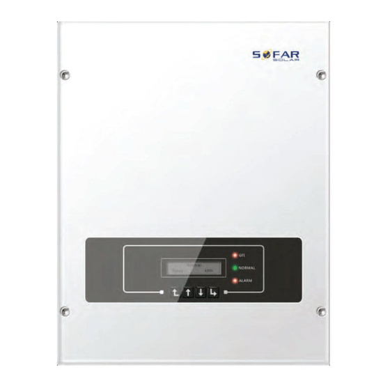
SOFAR 3K~6KTLM-G2 6. Operation interface Outlines of this chapter This section introduces the display, operation, buttons and LED indicator lights of SOFAR 3K~6KTLM-G2 Inverter. 6.1. Operation and Display Panel Buttons and Indicator lights Key-button: · Back :to return to previous menu or enter into main menu from the standard interface. -
Page 45: Standard Interface
User manual SOFAR 3K~6KTLM-G2 ·Warning Light (RED) ON: ‘Fault’ or ‘Permanent’ state OFF: ‘Normal’ state ·GFCI Warning Light (RED) ON: ‘ID12: GFCI Fault’ or ‘ID20: GFCI Device Fault’ OFF: GFCI normal 6.2. Standard Interface - 41 - Copyright © Shenzhen SOFARSOLAR Co., Ltd... - Page 46 User manual SOFAR 3K~6KTLM-G2 When power-on, LCD interface displays INITIALIZING, refer below picture. when control board successfully connected with communication board, the LCD display the current state of the inverter,display as shown in the figure below. - 42 - Copyright © Shenzhen SOFARSOLAR Co., Ltd...
- Page 47 User manual SOFAR 3K~6KTLM-G2 Inverter states includes: wait、check、normal、fault and permanent Wait:Inverter is waiting to Check State at the end of reconnection time. In this state, grid voltage value is between the max and min limits and so on; If not, Inverter will go to Fault State or Permanent State.
-
Page 48: Main Interface
User manual SOFAR 3K~6KTLM-G2 6.3. Main Interface Normal ------Press “back” 1.Enter Setting 2.Event List 3.SystemInfo 4.Display Time 5.Software Update (A) “Enter Setting” Interface as below: 1.Enter ------Press “back” Setting 1.Set time 12.Set Safety Voltage 2.Clear Energy 13.Set Safety Frequency 3.Clear Events 14.Insulation Resistance... - Page 49 User manual SOFAR 3K~6KTLM-G2 Set the system time for the inverter. 2. Clear Energy Clean the inverter of the total power generation. 3. Clear Events Clean up the historical events recorded in the inverter. 4. Set Country Set up the safety regulation country that meets the current use conditions and requirements.
- Page 50 Default 01. 9. Set Input mode Input mode selection: SOFAR 3K~6KTLM-G2 inverter has 2 MPPT channels, the 2 MPPT can operate independently, also can operate in parallel. If the PV strings are connected in parallel outside the inverter, you should choose the "in parallel mode", otherwise use the default setting.
- Page 51 User manual SOFAR 3K~6KTLM-G2 17. Reflux Power Enable or disable the anti-reflux function of the inverter, and set the reflux power.This function need to be used with external CT, please refer to this manual 4.5 RS485, CT, inverter logic interface connection for details.
-
Page 52: Update Software Online
Step 2 Insert the SD card into the compute. Step 3 SOFAR SOLAR will send the Software code to the user who needs to update. After user receive the file,please decompressing file and cover the original file in SD card. - Page 53 User manual SOFAR 3K~6KTLM-G2 Step 5 Then turn on DC switch and enter into the online upgrade to the main menu"5.Software Update"in the LCD display program[6.3(E)].The method to enter the menu can refer to operation interface of LCD. Step 6 Input the password, if password is correct,and then begin the update process,the original password is 0715.
-
Page 54: Trouble Shooting
User manual SOFAR 3K~6KTLM-G2 7. Trouble shooting Outlines of this chapter This topic describes how to perform daily maintenance and troubleshooting to ensure long term proper operation of the inverter. 7.1. Trouble shooting This section contains information and procedures for solving possible problems with the inverter. - Page 55 User manual SOFAR 3K~6KTLM-G2 Event Event List Event List Name solution List NO. description The power grid If the alarm occurs occasionally, the ID01 GridOVP voltage is too high possible cause is that the electric grid is abnormal occasionally. inverter automatically...
- Page 56 User manual SOFAR 3K~6KTLM-G2 low, then check the insulation conditions of PV cable. The input current is Check whether the input current is higher too high , and has than the maximum input current of inverters, ID14 HwBoostOCP happen hardware...
- Page 57 User manual SOFAR 3K~6KTLM-G2 6.3 (A) 10.Set Input mode of this manual. Internal faults of inverter, turn OFF the “DC The grid current is switch”, wait for 5 minutes, then turn ON the ID29 SwOCPInstan too high “DC switch”. Check whether the fault is rectified.
- Page 58 User manual SOFAR 3K~6KTLM-G2 the installation position exceeds the upper limit. OverTempFault_ The environment ID59 If yes, improve ventilation to decrease the temp is too high temperature. The grid current is UnrecoverHwAc too high,and has ID65 cause unrecoverable hardware fault...
-
Page 59: Maintenance
User manual SOFAR 3K~6KTLM-G2 Derating derated because of power when the frequency of electrical grid is the grid frequency is too high. too high Inverter records ID83 in case of remote The inverter has power derating operation. Check the wiring of... - Page 60 User manual SOFAR 3K~6KTLM-G2 around the heat sink for ventilation, check the heat sink for blockage (dust, snow, etc.) and clean them if they exist. Please clean the heat sink with an air blower, a dry & soft cloth or a soft bristle brush. Do NOT clean the heat sink with water, corrosive chemicals, detergent, etc.
-
Page 61: Technical Data
User manual SOFAR 3K~6KTLM-G2 8. Technical data Outlines of this chapter This topic lists the technical specifications for all SOFAR 3K~6KTLM-G2 inverters. 8.1. Input parameters (DC) SOFAR SOFAR SOFAR SOFAR SOFAR SOFAR Technical Data 3000TLM- 3600TLM- 4000TLM- 4600TLM- 5000TLM- 6000TLM- Max.DC power... -
Page 62: Output Parameters (Ac)
User manual SOFAR 3K~6KTLM-G2 8.2. Output parameters (AC) SOFAR SOFAR SOFAR SOFAR SOFAR SOFAR Technical Data 3000TLM- 3600TLM- 4000TLM- 4600TLM- 5000TLM- 6000TLM- Rated Output 3000W 3680W 4000W 4600W 5000W 6000W power Max.Output 3000VA 3680VA 4000VA 4600VA 5000VA 6000VA power Max.Output 13.7A... -
Page 63: Efficiency,Protection And Communication
User manual SOFAR 3K~6KTLM-G2 8.3. Efficiency,Protection and Communication SOFAR SOFAR SOFAR SOFAR SOFAR SOFAR Technical Data 3000TLM- 3600TLM- 4000TLM- 4600TLM- 5000TLM- 6000TLM- Max.Efficiency 98.0% Euro Efficiency 97.5% MPPT Efficiency >99.9% Self-consumption <1W at night Safety protection Anti islanding,RCMU,Ground fault monitoring... -
Page 64: General Date
User manual SOFAR 3K~6KTLM-G2 8.4. General Date SOFAR SOFAR SOFAR SOFAR SOFAR SOFAR Technical Data 3000TLM- 3600TLM- 4000TLM- 4600TLM- 5000TLM- 6000TLM- Topology Transformerless Ambient -25~60℃ temperature range Permissible 0~100% humidity range Noise figure <25dB DC Switch Optional Cooling Natural convection Max.Operating... -
Page 65: Quality Assurance
User manual SOFAR 3K~6KTLM-G2 9. Quality Assurance Standard warranty period The standard warranty period of inverter is 60 months (5 years).There are two calculation methods for the warranty period: 1. Purchase invoice provided by the customer: the first flight provides a standard warranty period of 60 months (5 years) from the invoice date;... - Page 66 User manual SOFAR 3K~6KTLM-G2 lightning protection devices are not included in the extended warranty period. If they fail during the extended warranty period, customers need to purchase and replace them from the our company. Once the extended warranty service is purchased, our company will issue the extended warranty card to the customer to confirm the extended warranty period.
Need help?
Do you have a question about the 3K~6KTLM-G2 and is the answer not in the manual?
Questions and answers