Table of Contents
Advertisement
Quick Links
®
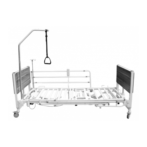
Houghton Electric Folding Bed
VG890W (White)
VG890B (Brown)
Lifting Pole (VG892J)
Cot Sides (Pair) (VG891C)
IV Pole (VG891V)
Mattress Retainer Bed Head (VG892H)
Mattress Retainer Bed Side (VG892HA)
This file is available to view and download as a PDF at
www.aidapt.co.uk. Sight impaired customers can use a
free PDF Reader (such as adobe.com/reader) to zoom in
and increase the text size for improved readability.
Fixing and Maintenance Instructions
Advertisement
Table of Contents

Subscribe to Our Youtube Channel
Related Manuals for aidapt VG890W


Summary of Contents for aidapt VG890W
- Page 1 Mattress Retainer Bed Side (VG892HA) This file is available to view and download as a PDF at www.aidapt.co.uk. Sight impaired customers can use a free PDF Reader (such as adobe.com/reader) to zoom in and increase the text size for improved readability.
-
Page 2: General Information
1. GENERAL INFORMATION PRODUCT LISTING VG890W Folding Electric Bed Light Oak (MXE-4XAG-B) VG890B Folding Electric Bed Brown (MBE-4XAG-B) VG891C European Side Rails (pair) (MBR-7) VG891V Two section IV Pole (MS-10) VG892H Mattress Retainer (bed head) VG892HA Mattress Retainer (bed side) - Page 3 • For use by adults • Heavy duty rectangular frame (epoxy coating) • Emergency stop button • Choice of colour for head and foot board • 4 braked castors • Drop down cot sides (optional) • Easy cleaning • Lifting pole (optional) •...
- Page 4 2. CONSTRUCTION The basic structure is as below Bed Body: Bed Deck Bed Board: Head & foot boards, four castors with brake Control Device: Hand control, emergency controller Side Rail: European side rails at each side of the bed Actuator: Independent actuator system under bed deck & bed boards UNFOLDED POSITION 1.
- Page 5 FOLDED POSITION Link Pin Packing Connector fig. 1 ASSEMBLY BREAKDOWN DIAGRAM Circuit is shown below; Motor Circuit Power Circuit Motor for Back Rest Plug Motor Circuit Controller Circuit Motor for Knee Rest Emergency Controller Motor Circuit Motor for Hi-Lo Hand Control Motor Circuit (with locking function Motor for Trendeleburg...
- Page 6 Emergency Controller 3. ASSEMBLY OF BED Recommended 2 person assembly. A video of the assembly is available at www.aidapt.com A. Installing the bed frame junction block Take out M10x20 bolt from the 50x30 rectangular tube of bed head frame, pull up the bed frame junction block, matching the first bolt hole and fasten using M10x20 with ø10 spring washer and ø10 flat washer.
- Page 7 B. Unpack the bed. C. Pull out 4 link pins from bed frame (see fig. 3) and take out the bed head frame and bed foot frame. fig. 3 Pull out the link pins D. Pull out 4 link pins from packing connector (see fig. 4) fig.
- Page 8 F. Connecting the bed frame. Insert the 50x30 rectangular tube of bed foot frame into the bed head frame junction block, tighten with screw (see fig. 6) fig. 6 G. Installing bed boards One hand holding up the bed head or foot board, the other hand lifting the bed frame, insert the installation bolt into the slot (see fig.
- Page 9 J. Connecting motor wire Insert the motor wire joint into the wire connecting hole of control box (see fig. 10) fig. 10 1. Hand control wire 2. Motor wire for height adjustment (bed foot) 3. Motor wire for height adjustment (bed head) 4.
-
Page 10: Parts And Accessories
2.8kg/pc (safe working load 75kg) INSTALLATION AND OPERATION OF SIDE RAILS A video of the assembly is available at www.aidapt.com A. At ideal position of the bed frame, insert the side rail base into 50x30 rectangular tube (see fig. 12) Put on with bolt, reinforce sleeve and ø8 flat washer then tighten the nut. - Page 11 B. Repeat step A to install the other side rail C. Pull out the handle button and pull down the side rail to lower it (see fig. 13). To raise the side rail, pull it up until a ‘click’ is heard to make the side rail lock at that position (see fig. 13). D.
-
Page 12: Operation
6. OPERATION All functions can be achieved by hand control (fig. 14) A. Press and hold the Back Up or Down button to adjust the back deck from 0º~73º. Keep pressing until you reach your ideal position. B. Press and hold the Knee Up or Down button to adjust the knee deck from 0º~37º. Keep pressing until you reach your ideal position. -
Page 13: Cleaning And Maintenance
fig. 15 Unlocking Status Locking Status H. Castors Push the bed to the destination, and step down on the brake pedal of the universal castor to prevent the bed movement. The castors are returned to move in any direction when the brake pedal is in level position. -
Page 14: Inspection And Maintenance
MATTRESSES fig. 16 The height of the mattress used is at least 20mm higher than any construction part (e.g., medical bed frame, side structure or the lowered side rails of the bed at the area of the mattress support platform) intended for the ingress/egress of the bed. 9. - Page 15 E. Manufacture Date Refer to the product label. 10. SAFETY Incompatible mattresses can create hazards. See marking plate (fig. 16) and mattress sticker Incompatible side rails can create hazards. See marking plate (fig. 17) Bed use only for movement within the patient room for cleaning or patient access.
- Page 16 • It is very important to read the manual and its safety instructions before use of the bed. If required the manual can also be downloaded from www.aidapt.com • Please refer to labels on equipment. SPECIFICATIONS & TECHNICAL DRAWINGS Ratings .........................
- Page 17 SPECIFICATIONS & TECHNICAL DRAWINGS (continued)
- Page 18 SPECIFICATIONS & TECHNICAL DRAWINGS (continued) This product comes with the symbols, icons and safety notes, indicating the follwoing meaning: Maximum patient weight: 200kg Safe working load: 235kg (including maximum patient weight, the mass of mattress, IV pole & lifting pole, and the safe working load of IV pole &...
- Page 19 SPECIFICATIONS & TECHNICAL DRAWINGS (continued) This product comes with the symbols, icons and safety notes, indicating the follwoing meaning: Marking of detachable side rails Serial number Supplier Manufacture date AUTHORISED REPRESENTATIVE IN THE EUROPEAN COUNTRY Consult the accompanying documents Copy of marking plates...
- Page 20 SPECIFICATIONS & TECHNICAL DRAWINGS (continued) Copy of marking plates...
-
Page 21: Troubleshooting
The information given in this instruction booklet must not be taken as forming part of or establishing any contractual or other commitment by Aidapt Bathrooms Limited, Aidapt (Wales) Ltd or its agents or its subsidiaries and no warranty or representation concerning the information is given.
Need help?
Do you have a question about the VG890W and is the answer not in the manual?
Questions and answers