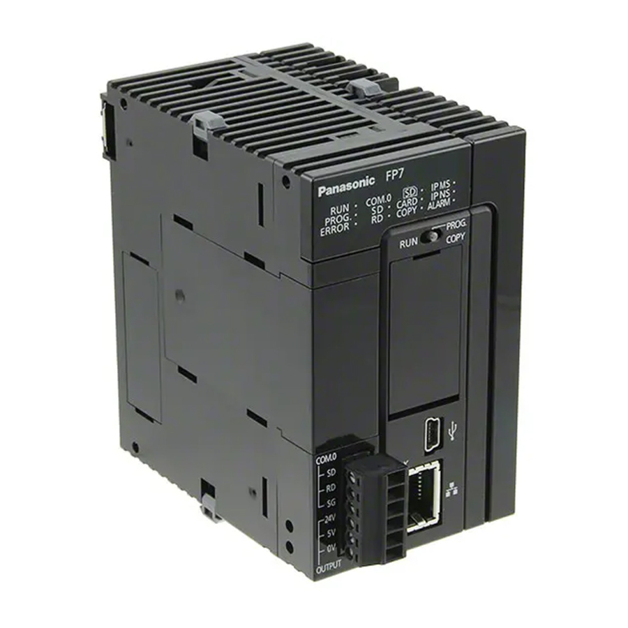
Panasonic FP7 User Manual
Analog output unit
Hide thumbs
Also See for FP7:
- Command reference manual (1222 pages) ,
- User manual (275 pages) ,
- Additional functions manual (45 pages)

Related Manuals for Panasonic FP7


Summary of Contents for Panasonic FP7
- Page 1 PROGRAMMABLE CONTROLLERS User's Manual FP7 Analog Output Unit ACGM0702V1.1EN 2021.05 industry.panasonic.eu...
- Page 2 This manual and everything described in it are copyrighted. You may not copy this manual, in whole or part, without written consent of Panasonic Electric Works Europe AG (PEWEU). PEWEU pursues a policy of continuous improvement of the design and performance of its products.
- Page 3 Indicates a hazardous situation which, if not avoided, could result in serious or moderate injury. CAUTION Indicates a hazardous situation which, if not avoided, could result in minor or moderate injury. NOTICE Indicates a property damage message. FP7 Analog Output Unit User's Manual...
- Page 4 Memory area tables Programming examples For documentation on other units used with the FP7, please refer to the hardware manual for that unit. All manuals can be downloaded from the Panasonic Web site (industry.panasonic.eu). FP7 Analog Output Unit User's Manual...
- Page 5 An insulated power supply with an internal protective circuit should be used (FP power supply). The power supply for the CPU is a non-insulated circuit, so if an incorrect voltage is directly applied, the internal circuit may be damaged or destroyed. FP7 Analog Output Unit User's Manual...
- Page 6 Also, if a password is forcibly bypassed, the program is delet- ed. Therefore, please note the password in a safe location. FP7 Analog Output Unit User's Manual...
-
Page 7: Table Of Contents
List of advanced configuration settings ..................... 29 Analog output in PROG mode ......................30 Offset/gain processing ........................31 Scale conversion ..........................32 Upper and lower limit clipping ......................33 Configuration by program ........................36 FP7 Analog Output Unit User's Manual... - Page 8 Digital values and control flags....................40 8.3.2 Status flags ..........................41 Unit memory addresses ........................42 8.4.1 Allocation of unit memory addresses ..................42 Bit settings in unit memory areas ...................... 42 Dimensions ............................44 FP7 Analog Output Unit User's Manual...
-
Page 9: Overview
Upper and In order to protect connected devices, this function limits the lower limit analog output value by clipping the digital input value if it ex- clipping ceeds the specified upper or lower limit. FP7 Analog Output Unit User's Manual... -
Page 10: Basic Operation
The following items can be set: Analog output in PROG mode Offset/gain processing Scale conversion Upper and lower limit clipping FP7 Analog Output Unit User's Manual... -
Page 11: Restrictions On Unit Combination
W Terminal block release lever – By lowering this lever, the terminal block can be removed from the unit without disconnecting the wiring. After in- stallation, push in the lock button at the bottom of the unit to lock in the terminal block. FP7 Analog Output Unit User's Manual... - Page 12 R Unit connector – Connects the unit to the internal circuit of I/O units and intelligent units. T Analog output terminal block – Remove the terminal block to facilitate wiring. Crimp terminals for M3 can be used. Y Fixing hook – Used to fix expansion units. FP7 Analog Output Unit User's Manual...
-
Page 13: Wiring
To reattach the terminal block, insert it all the way to its original N o t e position and press the lock button on the bottom of the unit. Then confirm that the terminal block is securely attached and cannot be removed. FP7 Analog Output Unit User's Manual... -
Page 14: Voltage Output
W D/A conversion circuit E Shield R Load Terminal layout Q Analog voltage output, channel 1 W Analog voltage output, channel 3 E Analog voltage output, channel 2 R Analog voltage output, channel 0 FP7 Analog Output Unit User's Manual... -
Page 15: Current Output
W D/A conversion circuit E Shield R Load Terminal layout Q Analog current output, channel 1 W Analog current output, channel 3 E Analog current output, channel 2 R Analog current output, channel 0 FP7 Analog Output Unit User's Manual... - Page 16 PLC wires, and do not bundle them with other wires. The NC terminals of the output terminal block are unused. Do not use these terminals to connect wires because some of the terminals are connected internally. FP7 Analog Output Unit User's Manual...
-
Page 17: I/O Allocation
Example: If the first word number is 10, the address number for the digital input value on channel 0 will be WY10. FP7 Analog Output Unit User's Manual... -
Page 18: Status Flags
Address Name Channel 0 Channel 1 Channel 2 Channel 3 WX0 X0 WX1 X10 WX2 X20 WX3 X30 Error flag Upper limit clipping flag Lower limit clipping flag X3–XF X13–X1F X23–X3F X33–X3F Not used FP7 Analog Output Unit User's Manual... - Page 19 TRUE when the digital input value exceeds the upper limit clipping value, provided that the clipping function is active. Lower limit clipping flag TRUE when the digital input value drops below the lower limit clipping val- ue, provided that the clipping function is active. FP7 Analog Output Unit User's Manual...
-
Page 20: Operation
E Analog signal Sample program The digital input values to the analog output unit are stored by channel in four different variables. They will be written to the CPU's memory areas DIXWY0, DIXWY2, DIXWY4, and DIXWY6. FP7 Analog Output Unit User's Manual... -
Page 21: Conversion Time
Operation POU Header LD Body 4.2 Conversion time Conversion time varies with the selected configuration settings. Conversion processing To speed up conversion, disable "Conversion processing" for all unused channels. FP7 Analog Output Unit User's Manual... - Page 22 CPU will only be processed by the analog unit after D/A con- version has been completed. Q Digital input value, channel 0 of CPU W CPU processing cycles E I/O refresh R Conversion processing T Analog signal, channel 0 of analog output unit FP7 Analog Output Unit User's Manual...
-
Page 23: Conversion Characteristics
Chapter 5 Conversion characteristics 5.1 Voltage range 5.1.1 -10 to +10V (0.32mV, 1/62500) Output range: -10 to +10V Digital input value n Analog output value (V) +31250 +25000 +18750 +12500 +6250 -6250 -12500 -18750 FP7 Analog Output Unit User's Manual... -
Page 24: To +10V (0.32Mv, 1/31250)
Output range: 0 to +10V Digital input value n Analog output value (V) +31250 +25000 +18750 +12500 +6250 When exceeding the rated range Digital input value Analog output value (V) +32500 +10.4 -1250 -0.4 FP7 Analog Output Unit User's Manual... -
Page 25: To +5V (0.16Mv, 1/31250)
Output range: 0 to +5V Digital input value n Analog output value (V) +31250 +25000 +18750 +12500 +6250 When exceeding the rated range Digital input value Analog output value (V) +32500 +5.2 -1250 -0.2 FP7 Analog Output Unit User's Manual... -
Page 26: To +5V (0.16Mv, 1/25000)
5.1.4 1 to +5V (0.16mV, 1/25000) Output range: 0 to +5V Digital input value n Analog output value (V) +25000 +18750 +12500 +6250 When exceeding the rated range Digital input value Analog output value (V) +26250 +5.2 -1250 FP7 Analog Output Unit User's Manual... -
Page 27: Current Range
Output range: 0 to +20mA Digital input value n Analog output value (mA) +31250 +25000 +18750 +12500 +6250 When exceeding the rated range Digital input value Analog output value (mA) +32500 +20.8mA -1250 -0.8mA FP7 Analog Output Unit User's Manual... -
Page 28: To +20Ma (0.64Μa, 1/25000)
5.2.2 +4 to +20mA (0.64μA, 1/25000) Output range: +4 to +20mA Digital input value n Analog output value (mA) +25000 +18750 +12500 +6250 When exceeding the rated range Digital input value Analog output value (mA) +26250 +20.8mA -1250 +3.2mA FP7 Analog Output Unit User's Manual... -
Page 29: Unit Configuration
Stop output in PROG mode value/Hold user-defined value Digital input -10...+10V: -32500 to value in PROG +32500 mode 0...+10V/0...+5V/0...+20mA: 0 to +32500 +1...+5V/+4...+20mA: 0 to +25000 Offset/gain Disable/Enable Disable processing Offset value -3000 to +3000 FP7 Analog Output Unit User's Manual... -
Page 30: Analog Output In Prog Mode
If "Stop output" has been set, the output will turn to FALSE (0V or 0mA) when the PLC is switched to PROG mode. The output will turn to FALSE (0V or 0mA) if an error occurs. FP7 Analog Output Unit User's Manual... -
Page 31: Offset/Gain Processing
The gain value slope can be changed in a range of 0.9x–1.1x. Q Gain adjustment W Gain 1.1x E Gain 0.9x Offset and gain processing is executed on a channel-by-channel basis. FP7 Analog Output Unit User's Manual... -
Page 32: Scale Conversion
Scale conversion Disable Select "Enable" Upper limit of 10000 To apply the setting, "Scale conversion" must be ena- scale bled. Setting range: -30000 to +30000 (specified with a Lower limit of signed integer) scale FP7 Analog Output Unit User's Manual... -
Page 33: Upper And Lower Limit Clipping
The lower limit clipping flag will turn to TRUE if the digital input value is smaller than the lower limit. To use the function, you must enable "Upper and lower limit clipping" in the "Analog unit settings" dialog and turn the clipping control flag to TRUE. FP7 Analog Output Unit User's Manual... - Page 34 Set the lower limit of the digital input value. value Setting range: -32500 to +32500 (specified with a signed integer) Upper and lower limit clipping is applied to the unscaled value. N o t e FP7 Analog Output Unit User's Manual...
- Page 35 0 is activated. When bResetClippingControlChannel0 turns to TRUE, the function is deactivated. bUpperLimitDetectedChannel0 turns to TRUE when the upper limit is reached. bLowerLimitDetectedChannel0 turns to TRUE when the lower limit is reached. FP7 Analog Output Unit User's Manual...
-
Page 36: Configuration By Program
After the configuration has been updated, unit memory UM00028 will be set to 0. Sample program (AFP7AD4H) Make the following settings by user program: Analog output processing, channel 0–1: Enable Analog output processing, channel 2–3: Disable Range setting: 4–20mA POU Header FP7 Analog Output Unit User's Manual... - Page 37 When bConfigure turns to TRUE and 16#55AA is written to unit memory UM00028, the configuration is updated. When the update is complete, 0 is written to UM00028 and writing of the output data starts. FP7 Analog Output Unit User's Manual...
-
Page 38: Troubleshooting
Check that the impedance of the input device is 500Ω or below if a cur- rent output range has been set. Check that the output is not short-circuited. Check that the digital input value is within the range. Check the configuration settings. FP7 Analog Output Unit User's Manual... -
Page 39: Specifications
+4 to +20mA (1/25000) Conversion time Voltage output 25µs/channel Current output Total accuracy Max. ±0.1% F.S. at +25°C Max. ±0.3% F.S. at 0°C to +55°C Output impedance (Voltage output) Max. 0.5Ω Max. output current (Voltage output) 10mA FP7 Analog Output Unit User's Manual... -
Page 40: I/O Allocation
Channel 2 Channel 3 WY0 Y0–YF WY2 Y20–Y2F WY4 Y40–Y4F WY6 Y60–Y6F Digital input value (16 bits) WY1 Y10 WY3 Y30 WY5 Y50 WY7 Y70 Clipping control flag Y10–Y1F Y31–Y3F Y51–Y5F Y71–Y7F Not used FP7 Analog Output Unit User's Manual... -
Page 41: Status Flags
X33–X3F Not used Error flag TRUE when an error has occurred. Upper limit clipping flag TRUE when the digital input value exceeds the upper limit clipping value, provided that the clipping function is active. FP7 Analog Output Unit User's Manual... -
Page 42: Unit Memory Addresses
8.5 Bit settings in unit memory areas Individual settings (settings per channel) The unit memory addresses are listed in ascending order for the supported channels (e.g. first unit memory address applies to channel 0, second to channel 1 etc.). FP7 Analog Output Unit User's Manual... - Page 43 UM00140 UM 00111 Digital input value in Setting range: UM 00121 PROG mode -10...+10V: -32500 to +32500 UM 00131 0...+10V/0...+5V/0...+20mA: 0 to +32500 UM 00141 +1...+5V/+4...+20mA: 0 to +25000 (specified with a signed integer) FP7 Analog Output Unit User's Manual...
-
Page 44: Dimensions
Specifications 8.6 Dimensions FP7 Analog Output Unit User's Manual... - Page 45 Record of changes Manual No. Date Description of changes ACGM0702V1EN 07/2015 First edition 05/2021 Updated company address and Web site ACGM0702V1.1EN...
Need help?
Do you have a question about the FP7 and is the answer not in the manual?
Questions and answers