Table of Contents
Advertisement
Available languages
Available languages
Quick Links
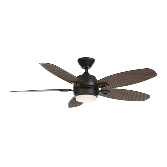
Item #1005 820 129
Model #52179
UL Model 52-KRAB
USE AND CARE GUIDE
DANIEL ISLAND 52-INCH CEILING FAN
Questions, problems, missing parts? Before returning to the store,
call Home Decorators Collection Customer Service
8 a.m. - 7 p.m., EST, Monday-Friday, 9 a.m. - 6 p.m., EST, Saturday.
1-800-986-3460
HOMEDEPOT.COM/HOMEDECORATORS
To view an instructional video on how to install this product:
1. Go to www.homedepot.com and enter either the Item or Model number, found in the top
right corner of the cover of this instruction manual, in the search eld.
2. Click on your product from the list of search results and click on the video link in the
"Product Overview" section.
THANK YOU
We appreciate the trust and confidence you have placed in Home Decorators Collection through the purchase of this ceiling fan. We strive
to continually create quality products designed to enhance your home. Visit us online to see our full line of products available for your home
improvement needs. Thank you for choosing Home Decorators Collection!
Advertisement
Chapters
Table of Contents

Related Manuals for HOMEDEPOT 1005 820 129


Summary of Contents for HOMEDEPOT 1005 820 129
- Page 1 To view an instructional video on how to install this product: 1. Go to www.homedepot.com and enter either the Item or Model number, found in the top right corner of the cover of this instruction manual, in the search eld.
-
Page 2: Table Of Contents
Table of Contents Table of Contents ..............2 Assembly ................7 Safety Information ............... 2 Operation ................13 Warranty ................3 Care and Cleaning ............. 15 Pre-Installation ..............3 Troubleshooting ..............15 Installation ................6 Safety Information READ AND SAVE THESE INSTRUCTIONS. WARNING: To reduce the risk of personal injury, do not bend the blade brackets (also referred to as flanges) during assembly or after installation. -
Page 3: Warranty
This warranty gives specific legal rights, and you may also have other rights that vary from state to state. This warranty supersedes all prior warranties. Shipping costs for any return of product as part of a claim on the warranty must be paid by the customer. Contact the Customer Service Team at 1-800-986-3460 or visit www.HomeDepot.com/homedecorators. Pre-Installation... - Page 4 Pre-Installation (continued) HARDWARE INCLUDED NOTE: Hardware not shown to actual size. Part Description Quantity Hanger pin Locking pin Plastic wire connecting nuts Blade bracket screws...
- Page 5 Remote control Blade arm Extension lead wire Battery IMPORTANT: This product and/or components are governed by one or more of the following U.S. Patents: 5,947,436; 5,988,580; 6,010,110; 6,046,416; 6,210,117 and other patents pending. HOMEDEPOT.COM/HOMEDECORATORS Please contact 1-800-986-3460 for further assistance.
-
Page 6: Installation
Installation MOUNTING OPTIONS WARNING: To reduce the risk of fire, electric shock or NOTE: You may need a longer downrod to maintain proper blade clearance when installing on a steep, sloped personal injury, mount to outlet box marked “Acceptable ceiling. The maximum angle allowable is 20° away from for fan support of 35 lbs (15.9 kg) or less”, and use screws horizontal. - Page 7 Insert the locking pin (BB) through the hole near the end of the hanger pin (AA) until it snaps into its locked position. □ Re-tighten the setscrew (HH) on the collar (GG) on top of the fan- motor assembly (E). HOMEDEPOT.COM/HOMEDECORATORS Please contact 1-800-986-3460 for further assistance.
- Page 8 Assembly - Hanging the Fan Attaching the fan to the electrical Hanging the fan □ Carefully lift the fan-motor assembly (E) up to the slide-on WARNING: To reduce the risk of fire, electric shock or personal mounting bracket (A). injury, mount to outlet box marked “Acceptable for fan support □...
-
Page 9: Assembly
□ Insert the narrow end of the receiver (K) (as shown, flat side towards the ceiling) into the slide-on mounting bracket until it rests on top of the ball/downrod assembly. HOMEDEPOT.COM/HOMEDECORATORS Please contact 1-800-986-3460 for further assistance. - Page 10 Assembly - Hanging the Fan (continued) Wiring the receiver to the Wiring the fan to the receiver household wiring WARNING: To avoid possible electrical shock, turn the NOTE: The fan comes with 12 in. lead wires for use with the electricity off at the main fuse box before wiring.
- Page 11 (G) indicating a secure connection. □ Visually inspect the top of the blade arms (F) to ensure the locking mechanism (UU) is securely in place. □ Repeat for the remaining blades. HOMEDEPOT.COM/HOMEDECORATORS Please contact 1-800-986-3460 for further assistance.
- Page 12 Assembly - Attaching the Accessories Installing the light kit pan □ Remove one screw (LL) from the black bracket below the fan motor assembly (E), and loosen but do not remove the other two screws. □ Connect the 9-pin plug exiting the bottom of the fan motor assembly (E) to the 9-pin plug from the light kit pan (H).
- Page 13 Push and release the button to cycle through the three color temperature options. Option 1: 2700K (Warm White). Option 2: 3000K (Soft White). Option 3: 3500K (Neutral White). Option 4: 4000/4100K (Cool White). Option 5: 5000K (Daylight). Option 6: 6500K (Cool Daylight). HOMEDEPOT.COM/HOMEDECORATORS Please contact 1-800-986-3460 for further assistance.
- Page 14 Assembly - Attaching the Accessories Mounting the remote control holder Screw cover plate NOTE: Screw wall anchors are included for extra support. The included screws are designed to screw easily into the wall. If you would like a more permanent or secure hold, install the wall anchors prior to attaching the wall cradle to the wall.
-
Page 15: Care And Cleaning
This device complies with Part 15 of the FCC Rules. Operation is subject to the following two conditions: (1) This device may not cause harmful interference, and (2) this device must accept any interference received, including interference that may cause undesired operation. HOMEDEPOT.COM/HOMEDECORATORS Please contact 1-800-986-3460 for further assistance. - Page 16 Questions, problems, missing parts? Before returning to the store, call Home Depot Customer Service 8 a.m. - 7 p.m., EST, Monday-Friday, 9 a.m. - 6 p.m., EST, Saturday. 1-800-986-3460 HOMEDEPOT.COM/HOMEDECORATORS Retain this manual for future use.
- Page 17 Para ver un video instructivo sobre cómo instalar este producto: 1. Visita www.homedepot.com e ingresa, en el campo de búsqueda, el número de artículo o modelo que aparece en la esquina superior derecha de la portada de este manual de instrucciones.
- Page 18 Tabla de contenido Tabla de contenido .............. 2 Ensamblaje ................7 Información de seguridad........... 2 Funcionamiento ..............13 Garantía ................3 Mantenimiento y limpieza ..........15 Preinstalación ..............3 Solución de problemas ............. 15 Instalación ................6 Información de seguridad LEE Y GUARDA ESTAS INSTRUCCIONES.
-
Page 19: Garantía
Esta garantía sustituye a todas las garantías anteriores. Los costos de envío en cualquier devolución de productos como parte de una reclamación tienen que ser pagados por el cliente. Comuníquese con el equipo de servicio al cliente por el 1-800-986-3460 o visite www.HomeDepot.com/homedecorators. Preinstalación... - Page 20 Preinstalación (continuación) HERRAJES INCLUIDOS NOTA: No se muestra el tamaño real de los herrajes. Pieza Descripción Cantidad Pasador de soporte Pasador de cierre Tuercas plásticas de conexión de cables Tornillos para soporte de aspas...
- Page 21 Extensión de cable terminal IMPORTANTE: Este producto y/o sus componentes están protegidos por Batería una o más de las siguientes patentes en EE. UU.: 5,947,436; 5,988,580; 6,010,110; 6,046,416; 6,210,117, así como otras patentes pendientes. HOMEDEPOT.COM/HOMEDECORATORS Para asistencia adicional, llama al 1-800-986-3460.
-
Page 22: Instalación
Instalación OPCIONES DE MONTAJE ADVERTENCIA: Para reducir el riesgo de incendio, descarga NOTA: Tal vez necesites un tubo bajante más largo para eléctrica o lesiones personales, instala solo en una caja mantener la altura mínima adecuada de las aspas, al instalar el ventilador en un techo inclinado. - Page 23 Inserta el pasador de cierre (BB) en el orificio cercano al extremo del pasador de soporte (AA) hasta que quede encajado en su posición. □ Vuelve a apretar el tornillo de fijación (HH) del collarín (GG) en la parte superior del conjunto motor-ventilador (E). HOMEDEPOT.COM/HOMEDECORATORS Para asistencia adicional, llama al 1-800-986-3460.
- Page 24 Ensamblaje - Cómo colgar el ventilador Cómo fijar el ventilador a la caja Cómo colgar el ventilador eléctrica □ Hay que levantar con cuidado el conjunto motor-ventilador (E) ADVERTENCIA: Para reducir el riesgo de incendio, descarga hasta el soporte de montaje deslizante (A). eléctrica o lesiones personales, instala solo en una caja eléctrica clasificada como “Apropiada para sostener ventiladores de 35 lb □...
-
Page 25: Ensamblaje
Inserta el extremo angosto del receptor (K) (como se muestra: el lado plano hacia el techo) en el soporte de montaje deslizante hasta dejarlo apoyado en la parte superior del conjunto tubo bajante/esfera. HOMEDEPOT.COM/HOMEDECORATORS Para asistencia adicional, llama al 1-800-986-3460. - Page 26 Ensamblaje - Cómo colgar el ventilador (continuación) Cómo cablear el receptor al Cómo cablear el ventilador al cableado del hogar receptor ADVERTENCIA: Para evitar posible descarga eléctrica, NOTA: El ventilador viene con cables terminales de 12 plg (30.5 desconecta la electricidad en la caja principal de cm) para usar con el conjunto de tubo bajante/esfera (B) de 4.5 fusibles antes de cablear.
- Page 27 (G) para indicar una conexión segura. □ Revisa la parte superior del brazo del aspa (F) para garantizar que el mecanismo de cierre (UU) esté asegurado en su lugar. □ Repite el procedimiento para las aspas restantes. HOMEDEPOT.COM/HOMEDECORATORS Para asistencia adicional, llama al 1-800-986-3460.
- Page 28 Ensamblaje — Cómo montar los accesorios Cómo instalar la carcasa del kit de luces □ Quita un tornillo (LL) del soporte negro debajo del conjunto motor- ventilador (E) y afloja los otros dos tornillos, pero sin quitarlos. □ Une el conector de 9 clavijas que sale de la parte inferior del conjunto del motor del ventilador (E) con el conector de 9 clavijas de la carcasa del kit de luces (H).
- Page 29 Opción 1: 2700K (Blanca cálida) Opción 2: 3000K (Blanca suave) Opción 3: 3500 K (Blanco neutro). Opción 4: 4000/4100K (Blanco frío) Opción 5: 5000K (Luz natural). Opción 6: 6500 K (Luz natural fría) HOMEDEPOT.COM/HOMEDECORATORS Para asistencia adicional, llama al 1-800-986-3460.
- Page 30 Ensamblaje — Cómo montar los accesorios Montaje del soporte del control remoto Placa de cubierta de los tornillos NOTA: Se incluyen anclajes de pared con tornillos para soporte adicional. Los tornillos incluidos están diseñados para atornillarse fácilmente en la pared. Si deseas una sujeción más permanente o segura, instala los anclajes de pared antes de fijar el soporte de pared a la pared.
-
Page 31: Solución De Problemas
Este dispositivo cumple con la Parte 15 de las Normas FCC. Su operación está sujeta a las dos condiciones siguientes: (1) Este dispositivo no debe causar interferencia dañina y (2) tiene que aceptar cualquier interferencia recibida, incluyendo aquella que pudiera afectar su funcionamiento. HOMEDEPOT.COM/HOMEDECORATORS Para asistencia adicional, llama al 1-800-986-3460. - Page 32 The Home Depot de lunes a viernes, entre 8:00 a. m. y 7:00 p. m. (hora del Este), y los sábados entre 9:00 a. m. y 6:00 p. m. (hora del Este). 1-800-986-3460 HOMEDEPOT.COM/HOMEDECORATORS Conserva este manual para uso futuro.
Need help?
Do you have a question about the 1005 820 129 and is the answer not in the manual?
Questions and answers