Advertisement
Quick Links
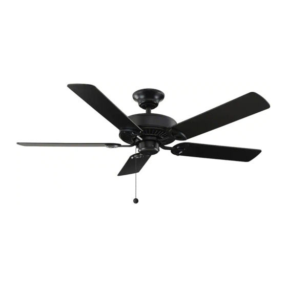
Item #722-493
Model #99432
INSTALLATION AND OPERATION
CEILING FAN REMOTE CONTROL
Questions, problems, missing parts? Before returning to the store, call Customer Service
8 a.m. - 6 p.m., EST, Monday-Friday, 9 a.m. - 6 p.m., EST Saturday
1-855-HD HAMPTON
HAMPTONBAY.COM
We appreciate the trust and confidence you have placed in Hampton Bay through the purchase of this remote control.
We strive to continually create quality products designed to enhance your home. Visit us online to see our full line of
products available for your home improvement needs.
Thank you for choosing Hampton Bay!
Installation (continued)
4
Wiring the receiver to the household wiring
WARNING: To avoid possible electrical shock, turn the
C (x3)
Outlet Box
electricity off at the main fuse box before wiring. If you
feel you do not have enough electrical wiring knowledge or
in the ceiling
experience, contact a licensed electrician.
(MM)
WARNING: Each wire not supplied with this fan is designed to
Black
Green
accept up to one 12-gauge house wire and two wires from the
fan. If you have larger than 12-gauge house wiring or more
(or Bare)
Black
than one house wire to connect to the fan wiring, consult an
electrician for the proper size wire nuts to use.
(or Red)
White
Green
IMPORTANT: Use the wire connecting nuts (AA) supplied with
your fan. Secure the connectors with electrical tape and
ensure there are no loose strands or connections.
Antenna
□ Spread the wires apart so that the green and white wires are on one
side of the outlet box and the black wire is on the other side.
□ Connect the green fan wires to the household ground wire (this may
be a green or bare wire) using a wire connecting nut (AA).
□ Connect the receiver black (or red) wire to the household black (hot)
wire using a wire connecting nut (AA).
□ Connect the receiver white wire to the household white wire (neutral)
B
wire using a wire connecting nut (AA).
□ Secure each wire connecting nut using electrical tape.
5
Wiring the fan to the receiver
Outlet box
C (x3)
in the ceiling
IMPORTANT: Use the wire connecting nuts (AA)
supplied with your fan. Secure the connectors
(MM)
with electrical tape and ensure there are no loose
strands or connections.
Green
□ Connect the fan motor white wire to the receiver white wire
using a wire connecting nut (AA).
B
Antenna
□ Connect the fan motor black wire to the receiver black wire
using a wire connecting nut (AA).
□ Connect the fan motor blue wire to the receiver blue wire
using a wire connecting nut (AA).
□ Secure each wire connecting nut using electrical tape.
□ Turn the wire connecting nut (AA) upward and push the wiring
into the outlet box (MM).
Black White
Blue
Safety Information
1.
YOU MUST SET CEILING FAN TO HIGH SPEED
WARNING: To avoid possible electrical shock,
AND LIGHT KIT (IF ANY) TO ON POSITION BEFORE
turn the electricity off at the main fuse box
before wiring. If you feel you do not have
OPERATING REMOTE CONTROL.
enough electrical wiring experience, contact a
2.
The supply to the remote control receiver should
licensed electrician.
be connected through a mains switch, i.e. existing
wall switch.
CAUTION: Incorrect wire connections will
damage this receiver.
3.
Disconnect from power supply at wall switch before
working on remote control receiver or ceiling fan.
CAUTION: To reduce the risk of fire or injury, do
4.
Install receiver into the ceiling fan canopy of the fan
not use this product in conjunction with any
variable (rheostat) wall control.
to ensure proper protection.
5.
This unit is to be used for the control of ceiling fan
NOTE: The battery will weaken with age and
and in a AC110/120V 60Hz power supply only.
should be replaced before leaking takes place
6.
Do not install in damp locations or immerse in
as this will damage the hand unit. Dispose of the
water. (For indoor use only.)
used battery properly, keep the battery out of the
7.
Do not pull on or cut leads shorter.
reach of children.
8.
Do not drop or bump the unit.
9.
Do not mix old and new batteries.
10. Do not mix alkaline, standard (carbon-zinc), or
rechargeable (ni-cad, ni-mh, etc.) batteries.
Warranty
The supplier warrants the remote control and receiver to be free from defects in workmanship and material present at
time of shipment from the factory for a period of one year after the date of purchase by the original purchaser. We agree
to correct such defects without charge or at our option replace with a comparable or superior model if the product is
returned. To obtain warranty service, you must present a copy of the receipt as proof of purchase. All costs of removing
and reinstalling the product are your responsibility. Damage to any part such as by accident or misuse or improper
installation or by affixing any accessories, is not covered by this warranty. Servicing performed by unauthorized
persons shall render the warranty invalid. There is no other express warranty. Home Depot hereby disclaims any and
all warranties, including but not limited to those of merchantability and fitness for a particular purpose to the extent
permitted by law. The duration of any implied warranty which cannot be disclaimed is limited to the time period as
specified in the express warranty. Some states do not allow a limitation on how long an implied warranty lasts, so the
above limitation may not apply to you. The retailer shall not be liable for incidental, consequential, or special damages
arising out of or in connection with product use or performance except as may otherwise be accorded by law. Some
states do not allow the exclusion of incidental or consequential damages, so the above exclusion or limitation may
not apply to you. This warranty gives specific legal rights, and you may also have other rights which vary from state to
state. This warranty supersedes all prior warranties. Shipping costs for any return of product as part of a claim on the
warranty must be paid by the customer.
Contact the Customer Service Team at 1-855-HD HAMPTON or visit www.HAMPTONBAY.COM
Operating Your Remote Control
1
Operating the remote control
-Press and release the
button to turn the fan on or off.
Press and hold the
button for 3 seconds to use the "walk away
time delay"; this will activate the light for 30 seconds (if you are using
dimmable bulbs the light will be activated at 50% brightness.
- Fan Speed - LED's on the fan speed button will illuminate to the
corresponding speed.
- Press button once - turns the fan on high speed.
- Press button twice - turns the fan on medium-high speed.
- Press button three times - turns the fan on medium-low speed.
- Press button four times - turns the fan on low speed.
Press button five times - fan will turn off.
- Light ON/OFF
Press and release the
button to turn the light on or off.
If you are using dimmable bulbs and you have previously set the dip
switch in your remote control to the "D" position, press and hold the
button to activate the dimmer function.
- Comfort Breeze
- Press and release the
button to enable Comfort
TM
Breeze
TM
; this will change your fan speed randomly, simulating a
relaxing breeze. To cancel this feature press
or
.
- Timer
- While the fan is on press button once - turns on a 2 hour run timer.
- While the fan is on press button twice - turns on a 4 hour run timer.
- While the fan is on press button three times - turns on a 8 hour run timer.
Pre-Installation
TOOLS REQUIRED
Flathead
Phillips
Adjustable
Electrical
Wire
screw-
screw-
wrench
tape
cutter
driver
driver
Step ladder
PACKAGE CONTENTS
C
D
B
A
Part
Description
Quantity
A
Remote control
1
IMPORTANT: This product and/or
B
Receiver
1
components are governed by one or more
C
AAA 1.5V battery
2
of the following U.S. Patents: 5,947,436;
5,988,580; 6,010,110; 6,046,416, 6,210,117
D
Plastic wire connector
5
and other patents pending.
E
White painting screw
1
F
Rubber isolated pad
2
Operating Fan with the WINK App
2
1
Downloading the WINK
Connecting to the WINK Hub
□ Ensure your WINK Hub is connected to WiFi
Application
by confirming the indicator light is a solid
□ Using your smart device, navigate to the
blue color.
application store (Apple App Store or Google
Play). Download the free WINK app and
□ With the app open, select "add a product."
create an account.
□ Choose the WINK Hub and follow the
instructions on the app to add your fan.
NOTE: Be sure your WINK Hub is plugged
in and within range of your fan. Refer to
Wink HUB user manual for the range.
Wi-Fi
3:17 PM
53%
CEILING FAN
Cancel
Help
Be sure your Hub is plugged in and
within range of your fan.
NEXT
3
Pairing the Fan to the WINK Hub
□ When instructed, turn on your fan. Once pairing is successful,
the fan will turn on at low speed and the light will blink 5 times.
Wi-Fi
3:19 PM
53%
Cancel
CEILING FAN
H e l p
Connect to Wink
NOTE: If using a dimmer with these lights, set dimmer at
SUCCESS!
highest setting for best results.
NOTE: Reset your fan if the pairing is taking longer than
expected. Turn off your fan for 3 seconds, then turn it back
on for 3 seconds. Repeat these steps 5 times. The light will
blink 3 times when factory reset is successful. If the pairing
failed, please reset the device to original setting and re-start
the pairing.
Fan Light Settings
• During set up, the customer is asked if the fan
NEXT
has a light kit.
Wink does not manufacture this product you have connected. By proceeding,
you acknowledge and accept that Wink does not guarantee the performance of
• If your fan has a light, select "Fan Light On."
this product you have connected to Wink.
• If your fan does not have a light, select "Fan
Light Off."
• Press SAVE to confirm.
Installation
1
Setting the codes on the
remote control and receiver
Setting the Code on the Remote
NOTE: The frequencies on your receiver
□ Remove the battery cover on the back of
and hand unit have been preset at the
the remote control by pressing firmly on the
factory. Before installing the receiver, make
arrow and sliding the cover off.
sure the dip switches on the receiver and
□ Slide the code switches to your choice of
hand unit are set to the same frequency.
either up or down. The factory setting is up.
The dip switches on the hand unit are
□ For fans with dimmable bulbs, slide the
located inside the battery compartment.
"Light Function" switch (O/D) to the position
marked "D". If you are using non dimmable
NOTE: The battery will weaken with age
bulbs slide the "Light Function" switch to the
and should be replaced before leaking
"O" position.
takes place as this will damage the hand
□ Install two 1.5V AAA batteries (included).
unit. Dispose of the used battery properly,
□ Replace the battery cover on the remote
keep the battery out of the reach of
control.
children.
Setting the Code on the Receiver
□ Slide the code switches on the receiver to
NOTE: It is imperative that the code used
the same positions as set on the remote
for both transmitter and receiver is exactly
control.
the same, otherwise remote controller will
not work.
Light Function
Switch
Receiver
D
O
FCC ID: KUJCE10319
IC ID:10786A-TR221A
MADE IN CHINA
MODELO: TR221A
FCC ID: KUJCE10319
IC ID: 10786A-TR221A
HECHO EN CHINA
FCC ID: KUJCE10319
MODè LE: TR221A
IC ID: 10786A-TR221A
FABRIQUé EN CHINE
Dip Switch
ON
1
2
3
4
Remote
Control
Control the Fan with the WINK App
4
Operating Your Remote Control
✓
S t a t u s
C o n n e c t e d
Fan Speed
Wi-Fi
3:19 PM
53%
• OFF -
Turns fan off
FANS
Name
• 1-
Turns the fan to Low speed.
Master Bedroom
• 2-
Turns the fan to Medium speed.
Model
• 3-
Turns the fan to Medium 2 speed.
• 4-
Turns the fan to High speed.
FAN SPEED
Ceiling Fan
• BREEZE- Randomly alternates fan speeds to
O
1
2
3
4
Breeze
Version
create an organic breeze effect.
FAN LIGHT
Software Version
Fan Light
O
On
Controller
.
Hub
• OFF/ON - Turns fan light off or on.
Settings
Select and slide to dim or brighten light.
>
Location
>
Set Timer
>
Fan Light Settings
Timer
Users
When on "fan control screen," press settings
Owner
+
Add a user
button
in upper right corner to display the
settings panel.
REMOVE THIS FAN
• Select fan to display control panel.
• Scroll down the control panel and select "Set
Timer."
Set Timer
• Scroll through the hours and minute columns
to select the duration of the timer.
• Press OK to start the timer.
3
hours
15
min
Cancel
Ok
Installation (continued)
2
Installing the rubber isolated pads
□ Loosen the two screws provided with the outlet
box; insert two rubber isolated pads (F) between
the mounting bracket and the outlet box; firmly
tightened the two screws.
3
Installing the receiver
WARNING: To reduce the risk of fire or electric
shock, remember to disconnect power. The
WINK antenna
electrical wiring must meet all local and
Receiver antenna
national electrical code requirements. The
(Leave connected and do not cut)
electrical source and fan must be 110/120 volt,
60Hz. Do not use this product in conjunction
with any variable wall control. Incorrect wire
connection can damage this receiver.
AAA
BBB
CAUTION: If fan or house wires are a different
color, have this unit installed by a licensed
electrician.
CAUTION: Do not install in a damp location or
immerse in water (For indoor use only). Do
not pull on or cut leads shorter. Do not drop or
Receiver antenna
bump the unit.
NOTE: The ceiling fan must be set at HIGH
speed and light kit (if installed) should be set to
the ON position.
WINK
NOTE: For better performance with the WINK
antenna
system, the T-Shaped antenna stick should
be mounted to the ceiling outside of the fan's
ceiling canopy using the pre-mounted double-
stick tape and wood screw (included).
□ Position the house supply wires (AAA) to one side
of the slide-on mounting bracket; position the fan
WINK antenna
wires (BBB) to the opposite side.
CEILING
mount to ceiling using wood screw
□ Insert the narrow end of the receiver (as shown, flat
side towards the ceiling) into the slide-on mounting
bracket until it rests on top of the ball/downrod
assembly. The canopy comes up to cover the
VIEW AFTER
receiver and bracket.
INSTALLATION
This equipment has been tested and found to comply with the limits for a Class B digital device, pursuant to Part 15 of the FCC Rules. These
limits are designed to provide reasonable protection against harmful interference in a residential installation. This equipment generates, uses
and can radiate radio frequency energy and, if not installed and used in accordance with the instructions, may cause harmful interference to
radio communications. However, there is no guarantee that interference will not occur in a particular installation. If this equipment does cause
harmful interference to radio or television reception, which can be determined by turning the equipment off and on, the user is encouraged to
try to correct the interference by one or more of the following measures:
--Reorient or relocate the receiving antenna.
--Increase the separation between the equipment and receiver.
--Connect the equipment into an outlet on a circuit different from that to which the receiver is connected.
--Consult the dealer or an experienced radio/TV technician for help.
CAUTION:
Any changes or modifications not expressly approved by the grantee of this device could void the user's authority to operate the equipment.
FCC ID: KUJCE10406, KUJCE10407
This device complies with Part 15 of the FCC Rules. Operation is subject to the following two conditions: (1) This device may not cause harmful
interference, and (2) this device must accept any interference received, including interference that may cause undesired operation.
Advertisement

Subscribe to Our Youtube Channel
Related Manuals for HOMEDEPOT EF200S-52


Summary of Contents for HOMEDEPOT EF200S-52
- Page 1 Safety Information Pre-Installation Installation Installation (continued) Item #722-493 YOU MUST SET CEILING FAN TO HIGH SPEED TOOLS REQUIRED Setting the codes on the Model #99432 WARNING: To avoid possible electrical shock, Installing the rubber isolated pads AND LIGHT KIT (IF ANY) TO ON POSITION BEFORE turn the electricity off at the main fuse box remote control and receiver before wiring.
- Page 2 To view an instructional video on how to install this product: 1. Go to www.homedepot.com and enter either the Item or Model number, found in the top right corner of the cover of this instruction manual, in the search eld.
-
Page 3: Table Of Contents
Table of Contents Table of Contents ..............2 Assembly ................7 Safety Information ............... 2 Operation ................13 Warranty ................3 Care and Cleaning ............. 14 Pre-Installation ..............3 Troubleshooting ..............14 Installation ................6 Safety Information READ AND SAVE THESE INSTRUCTIONS. WARNING: To reduce the risk of personal injury, do not bend the blade brackets (also referred to as All wiring must be in accordance with the National Electrical... -
Page 4: Warranty
This warranty supersedes all prior warranties. Shipping costs for any return of product as part of a claim on the warranty must be paid by the customer. Contact the Customer Service Team at 1-877-527-0313 or visit www.HomeDepot.com. Pre-Installation... - Page 5 Pre-Installation (continued) HARDWARE INCLUDED NOTE: Hardware not shown to actual size. Part Description Quantity Part Description Quantity Rubber gasket Locking pin Pull chain Blade attachment screws Plastic wire connectors Hanger pin...
- Page 6 Blade Ball/downrod assembly Blade bracket Canopy Canopy ring IMPORTANT: This product and/or components are governed by one or more of the following U.S. Patents: 5,947,436; 5,988,580; 6,010,110; 6,046,416, 6,210,117 and other patents pending. HOMEDEPOT.COM Please contact 1-877-527-0313 for further assistance.
-
Page 7: Installation
Installation MOUNTING OPTIONS WARNING: To reduce the risk of fire, electric shock NOTE: You may need a longer downrod to maintain or personal injury, mount to outlet box marked proper blade clearance when installing on a steep, sloped “Acceptable for fan support of 35 lbs. (15.9 Kg) or ceiling. -
Page 8: Assembly
Insert the locking pin (EE) through the hole near the end of the hanger pin (DD) until it snaps into its locked position. □ Re-tighten the two (2) setscrews (JJ) on the collar on top of the motor housing (E). HOMEDEPOT.COM Please contact 1-877-527-0313 for further assistance. - Page 9 Assembly - Close-To-Ceiling Mount Close-to-Ceiling Mounting Routing the wires □ □ Remove canopy ring (D) from the canopy (C) by turning the Remove three of the six screws (KK) and lock washers (LL) ring counterclockwise until it unlocks. (every other one) securing the motor collar to the top of the □...
- Page 10 □ If using close-to-ceiling mounting, hang the fan on the hook provided by utilizing one of the holes at the outer rim of the ceiling canopy (C). HOMEDEPOT.COM Please contact 1-877-527-0313 for further assistance.
- Page 11 Assembly - Hanging the Fan (continued) Making the electrical connection WARNING: Remove the rubber motor stops on the bottom of the fan before installing the blades or testing the motor. IMPORTANT: Use the wire connecting nuts (CC) supplied with your fan.
- Page 12 Step 1 “Prepairing for mounting”) into the holes in the canopy (C) and tighten firmly. □ Install the decorative canopy ring (D) by aligning the ring’s slots with the screws in the canopy (C). Rotate the ring clockwise to lock in place. HOMEDEPOT.COM Please contact 1-877-527-0313 for further assistance.
- Page 13 Assembly - Hanging the Fan (continued) Close-to-Ceiling mounting WARNING: The locking slots of the ceiling canopy are provided only as an aid to mounting. Do not leave the fan assembly unattended until all four canopy screws are engaged and firmly tightened. □...
-
Page 14: Operation
Cool weather - (Reverse) An upward airflow moves warm air off of the ceiling. This allows you to set your heating unit on a cooler set- ting without affecting your comfort. HOMEDEPOT.COM Please contact 1-877-527-0313 for further assistance. -
Page 15: Care And Cleaning
Care and Cleaning WARNING: Make sure the power is off before cleaning your fan. □ Because of the fan’s natural movement, some connections may become loose. Check the support connections, brackets, and blade attachments twice a year. Make sure they are secure. It is not necessary to remove the fan from the ceiling. □... - Page 16 Questions, problems, missing parts? Before returning to the store, call Home Depot Customer Service 8 a.m. - 6 p.m., EST, Monday-Friday, 9 a.m. - 6 p.m. EST, Saturday 1-877-527-0313 HOMEDEPOT.COM Retain this manual for future use. HOMEDEPOT.COM Please contact 1-877-527-0313 for further assistance.
Need help?
Do you have a question about the EF200S-52 and is the answer not in the manual?
Questions and answers