
Related Manuals for Milwaukee M12 CPL


Summary of Contents for Milwaukee M12 CPL
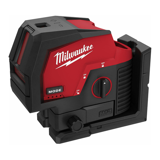
- Page 1 OPERATOR'S MANUAL Cat. No. M12 CPL M12™ CROSS LINE & PLUMB POINTS LASER WARNING To reduce the risk of injury, user must read and understand operator's manual.
- Page 2 • Maintain labels and nameplates. These carry The device produces visible laser important information. If unreadable or missing, WARNING beams, which are emitted from the contact MILWAUKEE for a replacement. ® tool. Use of controls or adjustments or CAUTION This device complies with AS/NZS 60825.1, •...
- Page 3 8. Threaded inserts recycling facility. 9. Magnets 10. Nail/Screw hole ASSEMBLY SPECIFICATIONS Cat. No............ M12 CPL Recharge only with the charger WARNING Volts............12V DC Battery Type ..........M12™ Charger Type..........M12™ manual supplied with your charger and battery.
- Page 4 2 hours to an performance of procedures other appropriate ambient temperature between -10°C to 40°C before turning on the tool. ous radiation exposure. If problem persists, please contact a MILWAUKEE ® Perform the Accuracy Field Check service facility for support. NOTICE...
- Page 5 See "Accuracy laser cross on the opposite wall B (point II). Field Check" for information. Should any deviation from listed product accuracy be found, please contact a MILWAUKEE service facility. ® Failure to do so could result in rejection of warranty claim.
- Page 6 Horizontal Leveling Accuracy free measuring space approximately 10m x 10m on a firm surface between two walls or structures A and B is required for the check. It is also suggested to mount the Laser Level to a Tripod for easy adjustment. Securely mount the tool on one side of the room and centered between walls A and B.
- Page 7 4. Rotate the tool 180°. Align the centre point of the 5. Mark the centre of the top plumb point on the reference line on the ceiling (point III). The maximum vertical deviation (d) is: d max = 2X H (door opening) x ±3.18mm ÷ 10m Example: for a door opening height of 2.05m, the maximum permitted deviation (d) is: The distance between points I and III on the...
- Page 8 Australia and New Zealand. SERVICE - AUSTRALIA and NEW ZEALAND MILWAUKEE ® prides itself in producing a premium quality product that is Nothing But Heavy Duty Your satisfaction with our products is very important to us! If you encounter any problems with the operation of this tool, please contact your authorised MILWAUKEE ®...
Need help?
Do you have a question about the M12 CPL and is the answer not in the manual?
Questions and answers