
Subscribe to Our Youtube Channel
Related Manuals for BiOptic Qsep Series


Summary of Contents for BiOptic Qsep Series
- Page 1 Qsep Operation Manual --- Hardware Revolution BiOptic Inc., 4F., No.108-3, Minquan Rd., Xindian Dist., New Taipei City 23141, Taiwan (R.O.C.) www.bioptic.com.tw...
-
Page 2: Table Of Contents
Welcome ........................3 Copyright and Trademarks ..................3 Symbols of Qsep Series ....................3 Limitation of Liability ....................4 Applications ........................4 Packing List ........................4 Cautions ........................6 ™ Instrument ....................9 1. Qsep ™ Front View ....................9 1.1 Qsep... -
Page 3: Welcome
Copyright and Trademarks Copyright © BiOptic Inc. All rights reserved. Reproduction, adaptation, or translation of this manual is prohibited without prior written permission of BiOptic Inc., except as allowed under the copyright laws. ™ Series and ™ are registered trademarks of BiOptic Inc. -
Page 4: Limitation Of Liability
BEFORE ATTEMPTING TO OPERATE THE INSTRUMENT, READ ALL PRODUCT MANUALS AND FOLLOW THE INSTRUCTIONS. BiOptic Inc. assumes no liability whatsoever for any personal injury, property damage, or other loss resulting from not complying or familiar with the manuals, or improper operation of the devices. - Page 5 Software Key (Basic edition) ™ Series Operation Qsep Installation Disc including Q-Analyzer™ for Qsep400 and Manual *Note: The Software key contains 8GB storage space, Q-Analyzer™ for Qsep400 and ™ Series Operation Manual, including Hardware version and Software version. Qsep...
-
Page 6: Cautions
™ Series away from other electronic device and voltage sources. Qsep Keep Only the components and consumables provided by BiOptic Inc. are suggested to use. DO NOT perform the following actions: •... - Page 7 ™ are high-voltage Multiple-channel electrophoresis system. Qsep Warning: Please follow the operation manual and laboratory safety guidelines for system operation. Do not remove covers. For operation and safety questions, please contact BiOptic Inc. at the official website or with your local BiOptic representatives.
- Page 8 System Overview ™ Series are a fully-automated CE system developed by BiOptic Inc., which uses Qsep pen-shaped disposable gel-cartridges to improve efficiency. Time-consuming manual procedures such as gel preparation, sample loading, and capillary changing are no longer required. Further, the information will be obtained easily with the fully- ™...
-
Page 9: Qsep ™ Front View
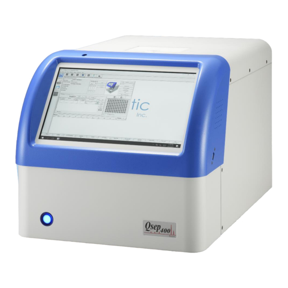
™ Instrument 1. Qsep Qsep ™ Front View Qsep Figure 1-1 ™ front view A. High voltage alert lamp: The red LED blinks when the high voltage source of the capillary electrophoresis is ON. B. Main Power switch: The blue LED lights up when it is turned on. C. - Page 10 Figure 1-2 Rotation platform...
-
Page 11: Qsep ™ Back View
™ Back View Qsep Qsep Figure 1-3 ™ back view A. Air pressure gauge: ™. Qsep Display the value of the pressure operating in B. Air flow Inlet Port: Connect to an external pump using an 1/8 inches tube. C. USB Port: Connect to a computer. -
Page 12: Qsep ™ Top View
Qsep ™ Top View Qsep ™ top view Figure 1-4 A. Cartridge door... -
Page 13: Installation Instruction
2. Installation Instruction A suitable operating environment is essential to ensuring the best performance of ™ Series. Qsep 2.1 Environment Requirements ⚫ ™ Series are 18°C~26°C (65°F ~78°F). Qsep The optimal operating temperature of ⚫ Qsep The optimal operating humidity of ™... -
Page 14: Power Considerations
2.2 Power Considerations Qsep ™ instrument is 24V DC, and the maximum current is The input voltage of 2.62A. A suitable power adapter with cord, SINPRO MPU60B-108, is included in the package (100~240V AC, 47~63Hz). The dimensions are 12.2cm(L)*5.2cm(W)*3.5cm(H) and weight of the instrument is 26Kg. Direct control the instrument with onboard computer. -
Page 15: Hardware Installation
2.3 Hardware Installation ™ Series instrument on a stable platform, and ensure it is away from water Qsep Place ™ Series need to be operated in a Qsep and any other high-power electronic devices. clean and well-ventilated environment. Remove the power adapter from the package and attach it with a suitable power cord. -
Page 16: Qsep ™ Quick Start
Qsep Quick Start ™ Follow the steps to start: Step 0. install the software and hardware. Step 1. Turn on the power Step 2. Launch Q-Analyzer for Qsep400 ※ The message box of "Purge function check" will pop-up after connected. Follow the instruction and proceed the check before using is recommended. - Page 17 Step 3-2. Add separation buffer into “S” well and add diH O into other wells ※ Fill each well of the buffer tray 80% full Step 4. Click “Change Buffer” Step 5. Allocate the buffer tray into the tray holder Step 6.
- Page 18 Step 8. Hold the plate by your hand and press down the tube of Alignment Marker tightly into the well by thumb Step 9. Allocate your samples (sample volume ≥ 20 μl) Spin down and make sure the sample is in the bottom of tube and no air bubble appears ※...
- Page 19 Step 13-1. New Cartridge Calibration New cartridge needs to be calibrated before using. Please proceed with the following steps ※ The storage and transportation condition may influence the cartridge and cause unstable current. If current (gray line) is unstable during HV check, please repeat this step 2-3 times.
- Page 20 Step 14. To analyze samples, click on the blank column and designate the sample locations, test method, and result name following steps 14-1 to 14-4 Step 14-1. “Sample Position” Mark the position of sample on the plate and then click “OK” Step 14-2.
- Page 21 Step 14-3. “Result Name” Enter the name of result file Step 14-4. “Para” Set the parameters (Baseline Factor, Peak Threshold, Calculate…) Calculate • Reference marker table: based on built-in size marker data • Create size marker: Place size marker at “SM” row on the holder, create your own size marker data Step 15.
- Page 22 Step 16. Check the results During Calibration Check the alignment markers have been placed in the correct position. Software will recognize two peaks from Alignment Marker signal. DO NOT use Size Marker or DNA sample to do “Calibrate”.
Need help?
Do you have a question about the Qsep Series and is the answer not in the manual?
Questions and answers