
Related Manuals for Promac 322BE1-BP


Summary of Contents for Promac 322BE1-BP
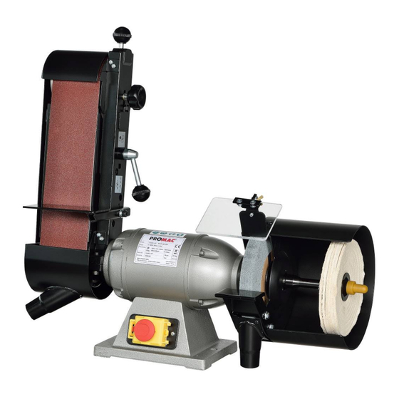
- Page 1 08-2020 Grinder & Sander 322BE1-BP France TOOL FRANCE 9 Rue des Pyrénées, 91090 LISSES, France www.promac.fr...
- Page 2 CE-Conformity Declaration CE-Konformitätserklärung Déclaration de Conformité CE Product / Produkt / Produit: Grinder & Sander 322BE1-BP Brand / Marke / Marque: PROMAC Manufacturer / Hersteller / Fabricant: TOOL FRANCE 9 Rue des Pyrénées, 91090 LISSES, France We hereby declare that this product complies with the regulations Wir erklären hiermit, dass dieses Produkt der folgenden Richtlinie entspricht...
- Page 3 Safety Rules for All Power Tools Read and become familiar with the entire instruction manual. Learn the tool’s applications, limitations and possible hazards. Earth all tools. If the tool is equipped with a three-prong plug. It must be plugged into a three-contact electric outlet.
- Page 4 Use the proper tool. Don’t force a tool to do a job for which it was not designed. Keep tools in top condition. Keep them clean and sharp for best and safest performance. Follow the instructions for changing accessories and lubricating. Secure all work.
-
Page 5: Table Of Contents
Many thanks for the confidence you have shown in us with the purchase of your new machine. This manual has been prepared for the owner and operators of a PROMAC grinder to promote safety during installation, operation and maintenance procedures. Please read and understand the information contained in these operating instructions and the accompanying documents. -
Page 6: General Safety Notes
3.2 General safety notes Metalworking machines can be dangerous if not used properly. Therefore, the appropriate general technical rules as well as the following notes must be observed. Install the machine so that there is sufficient space for safe operation and workpiece handling. -
Page 7: Remaining Hazards
Do not use the machine in a dump environment source. and do not expose it to rain. Always use a suitable dust collection device Machine only stock which rests securely on the table. Specifications regarding the maximum or minimum size of the workpiece must be 3.3 Remaining hazards observed. -
Page 8: Machine Specifications Technical Data
Machine specifications Technical data Modell ..........................322BE1-BP Motor kW ............................0.52 Power ..........................400 / 50 /3 Grinding Wheel Size mm ..................... 200 x 25 x 20.0 Speed (RPM) ..........................2850 Belt Size mm........................100 x 1000 Speed of Belt m/min ........................16 Work Space of Grinder mm .................... -
Page 9: Unpacking And Checking List
5. UNPACKING AND CHECKING LIST GRINDER ASSEMBLY MOP / BUFFER LOOSE PARTS IN RECTANGLE BOX Sanding Frame Sanding Belt P-100 Protection Cover Rubber Roller Assembly 9348... - Page 10 UNPACKING AND CHECKING LIST Bag 1:Eyeshield Q’ty : 1 set Bag 3..Socket Wrench, Open Spanner Ref No. Parts Name / Description Q’ty Ref No. Parts Name / Description Q’ty Socket Wrench Screw / Washer Open Spanner Eye Shield Screw (M6x20L) Nut (M6) Bag 4....Working Table Washer (M6x16x2t)
- Page 11 Loose Parts in Rectangle Box Figure Sanding Frame Title Sanding Belt Protection Cover Rubber Roller Assembly Q’ty ASSEMBLY CHART-SANDING DEVICE 1. Observe aluminum roller whether it’s tail end is at the right angle (90∘) to the frame. (Turn tracking knob clockwise may make the tail end of roller upward) 1.
- Page 12 ASSEMBLY CHART-SANDING BELT DEVICE BELT BALANCE Turn Tracking knob clockwise to make sanding belt toward right side or turn counter-clockwise to make belt toward left side Note: It is only allowed a tiny adjustment at each turn. Rotate belt by hand, meanwhile adjust tracking knob. Control the switch for a short on/off starting with left hand.
- Page 13 ASSEMBLY CHART-SANDING BELT DEVICE Use 6mm hex. Wrench to fix working table and it’s This working table is adjustable for the angles from accessories into hole at desired angles. 45∘~90∘. The 4 angle holes give different angles of 45∘,60∘,75∘& 90∘by the insertion of working table.
- Page 14 ASSEMBLY CHART-SANDING BELT DEVICE Curve Sanding 1. Put frame assembly to horizontal position. 1. This machine is designed to allow the 2. Loosen screw A showed in figure. sanding belt to be operated vertically or 3. Open the roller cover to proper position and fix it. horizontally at comfortable choice.
- Page 15 ASSEMBLY CHART-MOP/BUFFER...
- Page 16 GRINDING WHEEL’S REPLACEMENT 1. Remove adaptor assembly together with its' accessory. Take off wheel cover 2. Remove 3 screws of wheel cover. Hold grinding wheel and wrench to loosen Take off disc washer and wheel. grinder's nut. Note: To replace grinding wheel, act in reverse order.
-
Page 17: 2Be-Bp Exploded View
6. 322BE-BP Exploded View... -
Page 18: 2Be-Bp Part List
7. 322BE-BP Parts List Index Part Description Size Qty. 1 ....PM-322401 ....Eye Shield ........100x130x5mm ........ 1 2 ....PM-322402 ....Wheel Cover Assy ......for 8" ..........1 (Including #2 & #7) 3 ....PM-320008 ....Disc Washer ........1/2HP-5/8" ........2 3-1 .... - Page 19 Index Part Description Size Qty. 56 ....PM-321042 ....Adjustable Block ..................1 57 ....PM-321041 ....Snap Ring ........R35 ..........1 58 ....855174 ......Ball Bearing ........6202zz ..........2 59 ....PM-321040 ....Bush ..........Ø19.05x38.1mm ......1 60 ....
- Page 20 [ABOUT WORKSTAND] Optional List Unpacking and Checking *Universaal Workstand Parts Name Ref. Parts Name Ref. Q'ty Q'ty /Description /Description Stand Stand Leg (front & rear) Bottom Plate Stand Leg (left & right) Hex Bolt(M8x20L) Stand Top Spring Washer(M8) Washer(M8x30x3t) Sruare Neck Bolt(5/16"-18NCx5/8") Washer(M8x18x2t) Hex.Bolt(5/16"-18NCx2"..L type Hex Bolt(M8x35L)
- Page 21 DUST COLLECTION DEVICE [Optional] Unpacking and Checking List Ref. No. Parts Name / Description Q’ty Dust Collection Tank Dust Collection Bag Tank Cover, Collector Body with Motor 1 Chip Inlet (5”-4”) Chip Inlet (4”-1.5”) Hose (4”) Clamp (4.5”) Screw (M5x8) Screw (M6x16) 10 Washer (M6)
- Page 22 Electrical circuit diagram 322BE1-BP Electrical components Parts List Item Designation Description & Function Technical Data Remark Magnetic contactor three 400Vac, 6A phase Plug for supply for three 400Vac, 16A phase Cable three phase VCTF, 4 x 0.75mm...
- Page 23 Note:...
- Page 24 Environmental protection Protect the environment. Your appliance contains valuable materials which can be recovered or recycled. Please leave it at a specialized institution. This symbol indicates separate collection for electrical and electronic equipment required under the WEEE Directive (Directive 2012/19/EC) and is effective only within the European Union. Umweltschutz Schützen Sie die Umwelt! Ihr Gerät enthält mehrere unterschiedliche, wiederverwertbare Werkstoffe.
Need help?
Do you have a question about the 322BE1-BP and is the answer not in the manual?
Questions and answers