Advertisement
Quick Links
CA-HM-UNI-EVO.005
UNIVERSAL 2-DIN INSTALLATION KIT
Tools required (not included)
•
Phillips Screwdriver
•
4 mm Allen Head Screwdriver
•
Washer or Belt / Nut
Combination
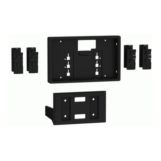
Kit components
a
a. Assembly
Mount
Secure the display brackets to the assembly mount using (4)
Allen head screws provided. Note: The brackets have a locking
pin on them which must face outwards.
Secure the assembly mount to thebrackets of your 2-DIN kit
using (4) Phillips screwsprovided. Route the RGB display cable
from the radio chassis, through the opening in
the assembly mount.
Please note
For steps 2 and 6, reference to the installation manual provided with the radio for which hardware
to use. The display screen and radio chassis use two different types of screws.
b
c
b. Display
c. Display
Housing
Trim Ring
1
3
Installation manual CA-HM-UNI-EVO.005 | Version 1.0
EN - Installation Manual
d
d. Display
Brackets
f
f. 4x #8 x 1/2"
Phillips Screws
Secure the radio chassis to the brackets
of your 2-DIN kit using (4) screws supplied
with the radio.
Optional extension cable CD-RGB150E available if required.
e
e. 5° Angle
Display Brackets
g
g. 4x 4mm
Allen Head Screws
2
Advertisement

Related Manuals for Pioneer CA-HM-UNI-EVO.005


Summary of Contents for Pioneer CA-HM-UNI-EVO.005
- Page 1 Secure the assembly mount to thebrackets of your 2-DIN kit Optional extension cable CD-RGB150E available if required. using (4) Phillips screwsprovided. Route the RGB display cable from the radio chassis, through the opening in the assembly mount. Installation manual CA-HM-UNI-EVO.005 | Version 1.0...
- Page 2 Plug the RGB display cable into the display, then slide and lock in place the display housing to the display brackets. Note: The locking pins can be pulled back to release the display housing. Installation manual CA-HM-UNI-EVO.005 | Version 1.0...
Need help?
Do you have a question about the CA-HM-UNI-EVO.005 and is the answer not in the manual?
Questions and answers