Table of Contents
Advertisement
Quick Links
Advertisement
Table of Contents

Related Manuals for Brightlink 4U


Summary of Contents for Brightlink 4U
-
Page 2: Preface
Preface Thank you for purchasing our splicing controllers, the company's products has been carried out strict safety testing before leaving the factory, to ensure safe operation, as well as prevent the risk of electric shock. "Splicing Controller User Manual" provide operational guidance for your device installation and use, to ensure that the product can be safe and trouble-free operation, please read the User Manual carefully before using this product. - Page 3 Relevant conventions about this Manual: In this Manual, if there are no special instructions, the products or splicing controllers mentioned refer to the splicing controller products described in this Manual. This Manual uses the following signs to indicate what should be noted in the operation process and the relevant instructions, the meaning of these signs are as follows::...
-
Page 4: Important Safety Tips
Important Safety Tips In order to ensure the reliable use of device and the safety of personnel, please observe the following in the installation, use and maintenance: ① The system must have a perfect grounding, otherwise not only cause signal interference, instability or mechanical damage, but also may cause personal accidents due to leakage of electricity. -
Page 5: Table Of Contents
RIEF INTRODUCTION OF PRODUCT 1.2 P ....................1 RODUCT TECHNICAL FEATURES 1.3 P ...................... 3 RODUCT STRUCTURE DIAGRAM CHAPTER 2 PRODUCT CHASSIS SPECIFICATION..............5 ....................5 RODUCT PECIFICATION -4U................5 IAGRAM OF THE RODUCT ANEL -8U................6 IAGRAM OF THE RODUCT ANEL -16U..............7 IAGRAM OF THE RODUCT ANEL -24U..............8... -
Page 6: Chapter 1 Product Overview
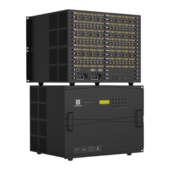
Figure 1-1 4U front panel diagram Splicing processor is suitable for the stability, security, concentration has a high demand for places, can be widely used in a variety of applications, for government agencies, transportation control, security monitoring, public safety, education and scientific research, news media, energy and other fields to bring a large screen display control solutions. - Page 7 Adopt standard chassis structure design, with 2U, 4U, 8U, 16U, 24U, 36U and other optional chassis specifications; special specifications of device can be developed, easy to configure.
-
Page 8: Product Structure Diagram
card decoding capability: 1080P@30HZ*36; the supporting front end is accessed in RTSP, GB/T 28181 mainstream IPC protocol; support a variety of video conferencing system SIP, H.323 protocol; Support software full-screen pre-monitoring echo function, which can visualize the input signal management, the current display status of the system can be viewed through the software interface ;... - Page 9 display device, a variety of front-end signal sources including DVI, Dual link, DVI, VGA, Ypbpr, HDMI, SDI, CVBS, HDBaseT, Optical Fiber and others, they are plugged into the splicing controllers through the corresponding input board card, and connected to the corresponding display devices (including DLP splicing, LCD splicing, LED and other display devices ) through the output end, to realize image arbitrary movement, scaling, roaming, superposition, multi-screen and other display functions.
-
Page 10: Chapter 2 Product Chassis Specification
Output ×20 80/80 Input ×29 Output ×15 116/60 Input ×15 Output ×29 60/116 Input ×40 Output ×40 160/160 36U Dual Input ×80 Output ×80 320/320 2.2 Diagram of the Product Back Panel -4U Figure 2-2 Schematic drawing of rear panel -4U... -
Page 11: Diagram Of The Product Back Panel -8U
2.3 Diagram of the Product Back Panel -8U Figure 2-3 Schematic drawing of rear panel -8U... -
Page 12: Diagram Of The Product Back Panel -16U
2.4 Diagram of the Product Back Panel -16U Figure 2-4 Schematic drawing of rear panel -16U... -
Page 13: Diagram Of The Product Back Panel -24U
2.5 Diagram of the Product Back Panel -24U Figure 2-5 Schematic drawing of rear panel -24U... -
Page 14: Diagram Of The Product Back Panel - 36U Dual
2.6 Diagram of the Product Back Panel - 36U Dual Figure 2-6 Diagram of the Back Panel - 36U Note: The above product diagrams are not the structural diagrams of the non-standard equipment, and please refer to the actual products ordered. -
Page 15: Chapter 3 Product Packing List
Chapter 3 Product Packing List LED Splicing Controller Host RS232 communication connecting line Equipment power cords USB for management software User manual, warranty card and quality certificate Notice: The product packing list is the list of general product equipment, which varies slightly according to the product and interface requirements, and if any missing or damaged parts are found. -
Page 16: Chapter 4 Product Installation
Chapter 4 Product Installation 4.1 Installation precautions To avoid damage to the device during installation, please read the installation instructions carefully before installing the device, including, but not limited to, the following security considerations: Warning: This product is electronic device; pay attention to water, electricity and other humid environment when using;... - Page 17 facilitate the safe movement of the device; The persons need to maintain consistent work steps when they are handling the device, remember not to be too fast or too slow to ensure the balance of the body, as well as avoid damage caused by the fall of device;...
-
Page 18: Installation Steps
4.2 Installation steps The splicing controller can be installed on any standard rack; consider the installation and implementation environment of the device during installation; the installation steps are as follows: 1) Place the device host smoothly on top of the mounting rack to ensure that it does not slide or fall off. -
Page 19: Communication And Connection Methods
Power outlet Equipment power interface Figure 5-1 Device Connection diagram Warning: The power supply system needs to be well grounded to determine the location of the power supply switch of the device, so that in the event of an accident, the power supply can be cut off in time. - Page 20 Signal ground null null null null Figure 5-2 9HDF Pin description 2) Connect to the control computer Using the RS-232 cable to connect the computer's serial communication port (COM1 or COM2) with the RS-232 communication port of the mosaic, the computer can be controlled by the splicing controller.
-
Page 21: Connection To The Signal Source
5.4 Connection to the signal source A splicing controller provides a different number of input, output interfaces according to different signal types, users can configure the corresponding input and output interfaces according to the needs of different sites. Device can provide including VGA, DVI, HDMI, SDI, CVBS, YPBPR, Duallink, DP, HDBaset, Fiber, IPV and other signal input interface, and VGA, DVI, HDMI, SDI, CVBS, Fiber, hdbaset and other signal output interface, through the corresponding video cable connected to the corresponding input interface, through the software operation to... - Page 22 2) D-Sub Signal Interface description Figure 5-5 D-Subinterface diagram D-Sub interface pin definition is shown in the following table: Function Function Reservations (different definitions) Green Digitally Blue Address code Address Code (ID Bit) Address code Self-testing (different Line synchronization definitions) Red Grand Field synchronization Address...
- Page 23 T.M.D.S.data 1 screen T.M.D.S.data 1- T.M.D.S.data 0+ DDC/CEC grounding T.M.D.S.data 0 screen + 5V DC power supply T.M.D.S.data 0- Hot swap detection T.M.D.S. clock + Note:The above interface usage and description is only part of the interface description, please the interface type of the purchased device shall be prevail.
-
Page 24: Chapter 6 Front Panel Description
Chapter 6 Front Panel Description 6.1 keys description Figure 6-1 Front panel diagram LCD, displaying the current status information and operation tips of the splicing controller. Input and output channel selection keys, used for setting the input and output channels of signals or for the number selection of status calling or saving. Use method: Switching mode: Press [NUMBER] key to specify an input + press [SWITCH] 0, 1, ...9... -
Page 25: Scene Keys
6.2 Scene keys The splicing controller can quickly invoke the scene through a front panel keys to quickly switch the currently saved scene to the display device, and the scene operates as follows: 1) Click the scene number you want to switch, click OK to switch the current scene to the display device, where: "Scene number"... -
Page 26: Chapter 7 Remote Control (Optional Device) Description
Chapter 7 Remote Control (optional device) Description This device provides an infrared receiving interface for the central control, and can also be remotely controlled with its own infrared remote control (optional). Infrared remote control mode provides a remote, wireless and fast way for system channel setting, which is mainly used to switch channel and channel switch control. -
Page 27: Chapter 8 Product Communication Protocol
Chapter 8 Product Communication Protocol The system has a variety of control types: serial port, key, infrared, network and mobile control terminal, in which serial port control is the basic control method. The communication serial port has a set of RS-232 series ports that can connect to the ASCII/16 terminal or any computer with this series of ports, and the command is transferred from the terminal or computer to the controller. - Page 28 Save scenario Save the preset This command is used to save the specified number <Enter> scenario scenario <Enter> Load scenario Close This command is used to call out the specified number <Enter> preset window scenario <Enter> Note: The baud rate in this communication protocol is 9600/115200bps,format to 1 starting bits, 8 bit data bits, 1 stop bits;...
-
Page 29: Appendix I Common Troubleshooting
Appendix I Common troubleshooting Troubleshooting Device Startup issues Whether the power cord can be used properly Device does not turn on Whether the power switch is turned on properly Whether the power cord is connected to the device ... - Page 30 Note:If there are other device failures, which are not listed in "common troubleshooting" in the use, please carefully check the device; please contact the company's after-sales service department if you have doubts.
-
Page 31: Appendix 2 Specification Parameters
Appendix 2 Specification Parameters 2-1, System parameters Case height 16UA 16UB Case Input slot specifica Output slot tion Input/output amount 16/16 36/32 80/80 116/60 60/116 160/160 320/320 DualLink/VGA/DVI/HDMI/Audio/DP/Ypbpr/CVBS/SDI/IP/H Signal type DBaseT/Fiber/USB, etc. Input Interface board 2/4/8 loops quantity card Input/out resolution board Signal type... - Page 32 Control RS232×2, 9-pin D-type male interface interface Serial port Baud rate 115200 control Special Panel touch, infrared, keys, serial ports, network, remote control, mode center control, mobile terminal Working -15-60 °C Operating temperature environm Working 10-90% non-condensing (RH) humidity Operatin Characteri Output 100-220V, AC...
-
Page 33: Module Parameters
Serial Computing Chip Monolithic Speed: 5.4 GH/S System bus scale System Bus Scale Single channel LVDS 4G/S speed 144-way x 4G/S 4U device 288-way x 4G/S 8U device 576-way x 4G/S 16U device 1440-way x 4G/S 24U device 2880-way x 4G/S... - Page 34 Clock 170M/S Single-linkage DVI input Interface DVI-I,a group consisting 4 interfaces resolution 800x600 to 1920x1200,special resolutions can be added clock 165M/S Dual-linkage DVI input Interface DVI-D,a group consisting 2 interfaces resolution 800x600 to 4096x1536,special resolutions can be added clock 2×165M/S DP input Interface DP,a group consisting 4 interfaces...
- Page 35 Signal type DVIHD Digital Video Signal clock 165M/S VGA output Interface HD15,a group consisting 4 interfaces Resolution 800×600 to 1920×1200 Signal type VGA Analog Video Signal clock 165M/S HDMI output Interface HDMI Type A,a group consisting 4 interfaces Resolution 800×600 to 1920×1080 Signal type DVI HD Digital Video Signal clock...
Need help?
Do you have a question about the 4U and is the answer not in the manual?
Questions and answers