
Related Manuals for Brightlink BL-VW22-4K30


Summary of Contents for Brightlink BL-VW22-4K30
- Page 1 BRIGHTLINK HDMI 2X2 4K Video Wall Controller with Mixed inputs MODEL : BL-VW22-4K30 Operating Instruction BRIGHTLINKAV.COM...
-
Page 2: Table Of Contents
Directory 1. FEATURES............................. 3 2. NOTICE............................3 3. SPECIFICATIONS......................... 3 4. PACKING CONTENTS......................... 4 5. PANEL DESCRIPTIONS.......................4 6. CONNECTING AND OPERATING....................4 7. Remote Control Instruction......................5 7.1 Video switching operation.......................5 7.2 Video control.......................... 6 7.3 EDID setup interface......................12 7.4 Audio control........................12 7.5 Setup interface........................14 7.6 INFO query information interface.................. -
Page 3: Features
1. FEATURES l Support Type C/DP port/HDMI input. l Select 1 of 4 source and distribute to 4 displays. l Create a 2x2 Video Wall Controller from any source to four displays. l Support multi-level cascading to create 3x3, 4x4...Video Wall (Max 10x10). l Support 180°... -
Page 4: Packing Contents
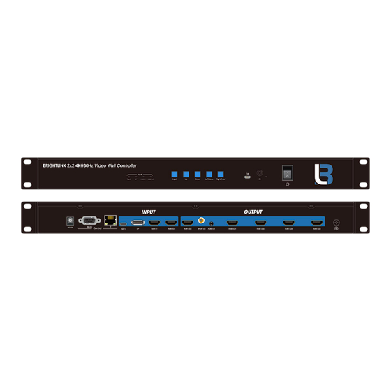
4. PACKING CONTENTS 1) Main Unit: HDMI 2X2 4K Video Wall Controller 2) 1x Power supply 12V2A 3) 4x Screws 4) 2x detachable mounting ears 5) 1x IR Cable 6) 1x Remote controller 5. PANEL DESCRIPTIONS Front Panel 1. Input status light 2. -
Page 5: Remote Control Instruction
3) Power up the Video Wall Controller. 4) Control the Video Wall Controller by Panel button / Remote / RS232 Command. 7. Remote Control Instruction 1. Power on/off 2. Mute 3. Source switching 4. Switch signal source of IN1 (TYPE C) 5. -
Page 6: Video Control
Video switching interface Operation mode: press the "INPUT" button directly and cycle through the input signal 7.2 Video control Press "Left/Menu" on the panel to enter the main menu. Main menu interface The function of the main menu is: 1. switching video signal source 2. - Page 7 Any input signal can be switched to all outputs. The signal switching includes four input signals, In1 is TYPE C input, In2 is DP input, In3 is HDMI 1 signal, In4 is HDMI 2 signal. It is the default HDMI IN1 input. Operation steps: 1.
- Page 8 the bottom color of Press the “up and down” button to select the "Preset" setting option, the selected input port becomes red, and the @ (Selected Symbol) is displayed. Click on the "ENTER" button to confirm and go to the next submenu Press the “up and down “button to select "1 x 1"...
- Page 9 Operational steps: In the main menu, select "Video" to press the "ENTER" button Press the “up and down” button to select 'Splicing' Click the "ENTER" button to enter the next sub-item Press the “up and down”button to select the "Set Up" setting option, and the bottom color of the selected setting option turns red Click on the "ENTER"...
- Page 10 Operational steps: 1. In the main menu, select "Video" to press the "ENTER" button 2. Press the”up and down”button to select Mirror 3. Click the "ENTER" button to enter the next sub-item 4. Press the “up and down” button to select settings such as "Normal", and the bottom color of the selected setting options becomes red 5.
- Page 11 set the margin between the two horizontal displays as required, and click the "ENTER" button to complete the setting 5.press the "Left/Menu" button to return to the previous menu, press the “up and down”button to select the "Y" setting option, click the "ENTER" button to enter the next subitem, click the “up and down”button, select and set the margins between the two vertical displays as required, and click the "ENTER"button to complete the settings...
-
Page 12: Edid Setup Interface
7.3 EDID setup interface The EDID setup interface can set the EDID, for each input port and the corresponding input source EDID separately. It also can be set the EDID for all input sources at the same time to select the built-in EDID (4K30HZ/108060HZ), copy EDID (CopyOut1,CopyOut2,CopyOut3,CopyOut4,Copy Loop) and the default EDID is 1080P60 Below are examples of built-in EDID4K@30 to input port 1:... - Page 13 Delay: There are 0-250 options,the unit is 10; The default settings are Unmute and delay 30. Take OUT1 as the output port, and set mute (mute) and Delay 10 (delay) as examples:...
-
Page 14: Setup Interface
Operational steps: 1. Select "Audio" in the main menu and press the "ENTER" button 2. Press the “up and down” button to select the Out 1 output (option 5 for all outputs). 3. Click the "ENTER" button to enter the next sub-item 4. - Page 15 Operational steps: 1. Select "Setup" in the main menu interface and press "ENTER" to confirm 2. Press the “up and down” button to select the "Baud"---baud rate setting 3. Click the "ENTER" button to enter the next sub-item 4. Press “up and down”button to select baud rate as needed. 5.
- Page 16 7.5.3.Modify IP: IP defaults to 192.168.1.168 Operational steps: 1. Select "Setup" in the main menu interface and press "ENTER" to confirm 2. Press the “up and down” button to select "TCP/IP" and press "ENTER" to confirm 3. For example, when the IP is modified to 192.168.1.168, press the “up and down”button to select IP [0], IP [1], IP [2], IP [3] to enter the next subitem (You can set a value from 0 to 255 in each subitemt, and the value you need to set can be quickly selected by long pressing the remote controller or the “up”...
- Page 17 7.5.4. Modify the subnet mask: the default is 255.255.255.0 Operation steps: 1. Select "Setup" in the main menu interface and press "ENTER" to confirm 2. Press the “up and down” buttons to select "TCP/IP" and press "ENTER" to confirm 3. For example: when the MASK is modified to 255.255.255.0, press the “up and down”...
- Page 18 7.5.5.Modify gateway: the default is 192.168.1.1 Operation steps: 1. Select "Setup" in the main menu interface and press "ENTER" to confirm 2. Press the “up and down” buttons to select "TCP/IP" and press "ENTER" to confirm 3. For example: when modification for GW 192.168.1.1, press the “up and down”button in turn select MASK [0], MASK [1], the MASK [2], MASK [3] to the next item (each item can be set up in the 0 ~ 255 a numeric value, can be long press the remote control, or press the “u”p button on the panel or “down”button...
- Page 20 7.5.7.Set the confirmation to take effect: after selecting the Apply option to confirm, the system will automatically judge the validity of the IP set by the user and prompt whether it is effective or not. Operation steps: 1. Select "Setup" in the main menu interface and press "ENTER" to confirm the key 2.
-
Page 21: Info Query Information Interface
Device functionality can be initialized. There are two options, yes or no, where the default is NO. 1. In the main menu, select "Setup" to press the "ENTER" button 2. Click the "ENTER" button to enter the next sub-item 3. Press the “up and down” button to select "No" or "Yes" 4. -
Page 22: Basic Information Interface
2. press the “up and down” button to select "System".Click "ENTER", you can view copyright, model, version number and other information 3. Click "Left/Menu" to return to the previous menu 4. Press “up and down” button to select "IP ".Click" ENTER "to confirm, you can view DHCP status, IP, MAC and other information 7.7 Basic information interface The interface reflects the current input and output basic video information. - Page 23 Multiple device local area networks control at the same time: Connecting to LAN to realize multi-user remote control devices (such as mobile phone, other PC) in Ethernet environment, it is necessary to ensure that the IP segment of the host is consistent with that of the connected LAN.In addition, the control computer network segment needs to be changed to be consistent with the host network segment, and the DHCP of the device needs to be opened.
-
Page 24: Interface Introduction
8.1 Interface Introduction 8.1.1. The icon The browser page TAB displays the logo and device name. 8.1.2. Status display instructions Click the navigation bar above, you can enter the corresponding operation interface; Do not click continuously;Click again after the setting is successful. If the setting is invalid, please click the button again. -
Page 25: Splicing Interface
8.2.2. Operational steps: Take the default IP address login as an example: (1) IP configuration: IP configuration is required, whether using click-out control or LAN multi-machine control, (2) After configuration, pls enter the default IP address into the browser, enter the web end login interface, enter account number: admin, password: 123456 click on... -
Page 26: Mirror Interface
8.3.2. Instructions for operation: Eg: The TYPEC as input source to achieve 2x2 video wall, which requires only one piece of equipment, Operational steps: Click the output section with the left mouse button, setting horizon =2, vertical =2, equipment =1(There is only one device.The cascade position must be 1, otherwise the setting is invalid);... -
Page 27: Edge Interface
2. Operating instructions Click on the corresponding button to send instructions in real time 8.5 Edge interface 1. Interface introduction: The interface is used to adjust the edge of the screen, with a parameter of 0~600, increasing or decreasing by 2 at a time. 2. -
Page 28: Edid Interface
8.7 EDID interface 8.7.1. Interface introduction: This interface sets the EDID of the input source. INPUT column: select the INPUT source >> the INPUT source(DP,type C,HDMI1/2) >> select the information of EDID; The Input interface will display which EDID is copied in real time. EDID can be set for different input sources, or the same EDID can be set for all input port. -
Page 29: Network Interface
8.8 Network interface 1. Interface description: It used to set up and display related IP information. 2. Operating instructions: MAC address can only be displayed and cannot be modified. Static IP: click DHCP button to adjust to DHCP off state. When using static IP, IP and other addresses can be modified. -
Page 30: Rs232
(you can only change the account name and password of the currently logged in account, which will take effect next time). 9. RS232 Function description: VW22 works normally to display images, plug in the USB to RS232 tool, double-click to open the software, and then enter the main interface of the software, as shown below: Instructions: 1. -
Page 31: Audio
3. A space should be added between the instruction header, first-level parameters and attribute parameters.Pleas check the instruction sheet for property parameters 5. Note: "/" indicates that this parameter is not used 10. Audio VW22 audio can be divided into two parts: HDMI audio output, audio separation output 10.1 HDMI audio output 1. -
Page 32: Firmware Upgrade
3. When copying EDID, digital audio and analog audio output is related to the TV on the input and copy port 11 Firmware upgrade 11.1 MCU burn 11.1.1. The APP burn Open the software UART_ISP.exe on the PC, select the correct port and baud rate 115200, enter A1_01 (_ represents space) in the port, then select the program (VW22_xxx_xxx_app_xxx.bin) in the path, and click update to complete the upgrade 11.2 GUI burn... - Page 33 11.2.2.Web burning Open the software UART_ISP.exe on the PC, select the correct port, baud rate 115200, enter F0_01(_for space)in the port and select the program(XXXX.html)in path, and click update to complete the upgrade.
-
Page 34: Connection Diagram
12. CONNECTION DIAGRAM MAINTENANCE Clean this unit with a soft, dry cloth. Never use alcohol, paint thinner of benzine to clean this unit. PRODUCT SERVICE 1) Damage requiring service: The unit should be serviced by qualified service personnel if: (a) The DC power supply cord or AC adaptor has been damaged; (b) Objects or liquids have gotten into the unit;... - Page 35 WARRANTY If your product does not work properly because of a defect in materials or workmanship, our Company (referred to as "the warrantor" ) will, for the length of the period indicated as below, (Parts(2)Year, Labor(90) Days) which starts with the date of original purchase ("Limited Warranty period"), at its option either(a) repair your product with new or refurbished parts, or (b) replace it with a new of a refurbished product.
Need help?
Do you have a question about the BL-VW22-4K30 and is the answer not in the manual?
Questions and answers