Table of Contents
Advertisement
Quick Links
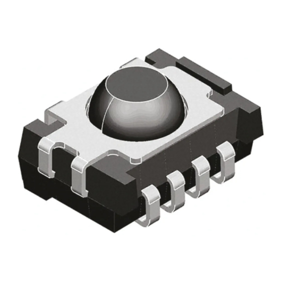
IR Receiver Modules for Remote Control Systems
MECHANICAL DATA
Pinning
1 = GND, 2 = N.C., 3 = V
, 4 = OUT
S
DESCRIPTION
The TSOP62.. series are miniaturized SMD-IR receiver
modules for infrared remote control systems. PIN diode and
preamplifier are assembled on lead frame, the epoxy
package is designed as IR filter.
The demodulated output signal can be directly decoded by a
microprocessor. TSOP62.. is the standard IR remote control
SMD-receiver series, supporting all major transmission
codes.
This component has not been qualified according to
automotive specifications.
PARTS TABLE
CARRIER FREQUENCY
30 kHz
33 kHz
36 kHz
36.7 kHz
38 kHz
40 kHz
56 kHz
BLOCK DIAGRAM
Input
AGC
PIN
Control circuit
16839-1
Document Number: 82177
Rev. 1.9, 21-Apr-09
4
3
2
1
16797
3
V
S
33 kΩ
4
OUT
-
Band
Demo
dulator
pass
1
GND
FEATURES
• Photo detector and preamplifier in one package
• Internal filter for PCM frequency
• Supply voltage: 2.7 V to 5.5 V
• Output active low
• Low power consumption
• High immunity against ambient light
• Low power consumption
• Compliant to RoHS directive 2002/95/EC and in
accordance to WEEE 2002/96/EC
SPECIAL FEATURES
• Improved immunity against ambient light
• Suitable burst length ≥ 10 cycles/burst
• Taping available for top view and side view assembly
STANDARD APPLICATIONS (AGC2/AGC8)
TSOP6230
TSOP6233
TSOP6236
TSOP6237
TSOP6238
TSOP6240
TSOP6256
APPLICATION CIRCUIT
17170_7
Transmitter
IR receiver
with
TSALxxxx
The external components R
to improve the robustnes against electrical overstress
(typical values are R
The output voltage V
below 1 V by the external circuit.
The capacitive load at the output should be less than 2 nF.
New TSOP62..
Vishay Semiconductors
R
1
V
S
C
1
OUT
V
O
GND
and C
are optional
1
1
= 100 Ω, C
= 0.1 µF).
1
1
should not be pulled down to a level
O
www.vishay.com
+ V
S
µC
GND
1
Advertisement
Table of Contents

Subscribe to Our Youtube Channel
Related Manuals for Vishay TSOP62 Series


Summary of Contents for Vishay TSOP62 Series
- Page 1 New TSOP62.. Vishay Semiconductors IR Receiver Modules for Remote Control Systems FEATURES • Photo detector and preamplifier in one package • Internal filter for PCM frequency • Supply voltage: 2.7 V to 5.5 V • Output active low • Low power consumption •...
-
Page 2: Absolute Maximum Ratings
New TSOP62.. IR Receiver Modules for Vishay Semiconductors Remote Control Systems ABSOLUTE MAXIMUM RATINGS PARAMETER TEST CONDITION SYMBOL VALUE UNIT Supply voltage (pin 3) - 0.3 to + 6.0 Supply current (pin 3) Output voltage (pin 4) - 0.3 to 5.5 Voltage at output to supply - 0.3 to (V... - Page 3 New TSOP62.. IR Receiver Modules for Vishay Semiconductors Remote Control Systems Optical Test Signal Correlation with Ambient Light Sources: 10 W/m² = 1.4 kLx (Std. illum. A, T = 2855 K) 10 W/m² = 8.2 kLx (Daylight, T = 5900 K) 600 µs...
- Page 4 New TSOP62.. IR Receiver Modules for Vishay Semiconductors Remote Control Systems 0° 10° 20° 30° 40° 50° 60° f = 38 kHz, E = 2 mW/m 70° 80° - Relative Transmission Distance Burst Length (number of cycles/burst) 16913 16801 Fig. 9 - Max. Envelope Duty Cycle vs. Burst Length Fig.
- Page 5 New TSOP62.. IR Receiver Modules for Vishay Semiconductors Remote Control Systems SUITABLE DATA FORMAT The TSOP62.. series is designed to suppress spurious output pulses due to noise or disturbance signals. Data and disturbance signals can be distinguished by the devices according to carrier frequency, burst length and envelope duty cycle.
-
Page 6: Reflow Soldering
New TSOP62.. IR Receiver Modules for Vishay Semiconductors Remote Control Systems PACKAGE DIMENSIONS in millimeters ± 0.5 Pick and place area. TT taping (1.4) 1.27 ± 0.5 3 x 1.27 = 3.81 0.5 A 5.51 Not indicated tolerances ± 0.3 Pick and place area. - Page 7 New TSOP62.. IR Receiver Modules for Vishay Semiconductors Remote Control Systems VISHAY LEAD (Pb)-FREE REFLOW SOLDER PROFILE max. 260 °C 255 °C 245 °C 240 °C 217 °C max. 20 s max. 100 s max. 120 s max. Ramp Up 3 °C/s max.
- Page 8 New TSOP62.. IR Receiver Modules for Vishay Semiconductors Remote Control Systems TAPING VERSION TSOP..TR Dimensions in millimeters 16585 www.vishay.com Document Number: 82177 Rev. 1.9, 21-Apr-09...
- Page 9 The standard packing units are labeled with standard bar code labels before transported as finished goods to warehouses. The labels are on each packing unit and contain Vishay Semiconductor GmbH specific data. Document Number: 82177 www.vishay.com Rev. 1.9, 21-Apr-09...
- Page 10 New TSOP62.. IR Receiver Modules for Vishay Semiconductors Remote Control Systems VISHAY SEMICONDUCTOR GMBH STANDARD BAR CODE PRODUCT LABEL (Finished Goods) PLAIN WRITING ABBREVIATION LENGTH Item-description Item-number Selection-code LOT-/serial-number BATCH Data-code 3 (YWW) Plant-code Quantity Accepted by Packed by Mixed code indicator...
-
Page 11: Esd Precaution
Proper storage and handling procedures should be followed to prevent ESD damage to the devices especially when they The Vishay Semiconductors standard bar code labels are are removed from the antistatic shielding bag. Electro-static printed at final packing areas. The labels are on each sensitive devices warning labels are on the packaging. - Page 12 Vishay disclaims any and all liability arising out of the use or application of any product described herein or of any information provided herein to the maximum extent permitted by law. The product specifications do not expand or otherwise modify Vishay’s terms and conditions of purchase, including but not limited to the warranty expressed...
Need help?
Do you have a question about the TSOP62 Series and is the answer not in the manual?
Questions and answers