
Related Manuals for AMT VAC COAT DTT


Summary of Contents for AMT VAC COAT DTT
- Page 1 Triple Source Thermal Evaporation Coater User Manual For technical and applications advice plus online order for spares and consumables parts visit www.vaccoat.com...
- Page 2 Vaccoat Ltd. is the owner and manufacturer of DTT Thermal evaporator. Vac Coat Ltd. 20, Dryden Rd., Harrow, HA3 7Jz, London/ UK Tel: +44 20 8427 8606 Mon: +44 7828 824 005 E-mail: Info@vaccoat.com Web: www.vaccoat.com For technical and applications advice plus online order for spares and consumables parts visit www.vaccoat.com Disclaimer The components and packages described in this document are mutually compatible and guaranteed to...
- Page 3 This Operating Manual is divided up into the following major sections, each section dealing with specific topics, as follows: Section 1: Content List of Figures List of Tables Section 2: Health and Safety It is important for all firm's product, which describe very important issues in the field of safety. ...
-
Page 4: Table Of Contents
1- Contents: Health &Safety ............................6 2.1- Safety Policy ............................. 6 2.2- Servicing ............................7 2.2.1- Disclaimer ............................. 7 2.2.2- Operators and Service Engineers ....................7 2.3- Hazard Signals and Signs ........................7 2.3.1- Hazard Signal Words ........................7 2.3.2- Hazard Labels Used on Equipment .................... - Page 5 5.4- Device Setting ..........................42 Maintenance ............................47 Target Installation and Replacement ....................47 Crystal Replacement ........................47 Cleaning the Device ........................49 Transportation and Handling ......................50 Troubleshooting the DSR3......................51 6-5-1- Thickness gauge troubleshooting..................... 51 6-5-2- Leakage and Leakage Detection ...................... 53 Appendix 1 ............................
- Page 6 Figure 5 -8: Turbo Molecular pump page ....................35 Figure 5 -9: Pressure Display in the main page ................... 36 Figure 5 -10: MFC (Mass Flow Control) Page .................... 37 Figure 5 -11: Deposition mode setting section in main page ............... 38 Figure ...
-
Page 7: 2- Health &Safety
2- Health &Safety The Vaccoat Company has provided maximum safety for its production systems and operators. It is required to read the complete user instruction before starting to work with the device. All service and repairs should only be performed by a qualified specialist. Vaccoat Company will not be liable for any loss or damage caused by repairs and services performed by an unauthorized or unqualified person. -
Page 8: Servicing
liable damage, injury consequential loss resulting from incorrect operation of the instrument or modification of the instrument. 2.2- Servicing 2.2.1- Disclaimer All service work on the equipment should be carried out by qualified personnel. Vaccoat Co. cannot be liable for damage, injury or consequential loss resulting from servicing from unqualified personnel. -
Page 9: 2- Hazard Labels Used On Equipment
DANGER- imminently hazardous situation unsafe practice that, avoided, will result in death or severe injury. WARNING - potentially hazardous situation unsafe practice that, avoided, could result in death or severe injury. CAUTION - potentially hazardous situation unsafe practice that, avoided, may result in minor or moderate injury or damage to equipment. 2.3.2- Hazard Labels Used on Equipment Several hazard symbols may be found on the equipment, they are shown in Table.1 with their meaning:... -
Page 10: Earth Connection
Potentially hazardous situation or unsafe practice that, if not Caution avoided, may result in minor or moderate injury or damage to equipment. 2.4- Earth connection The device must be connected to a plug with proper earth connection; this would prevent electrocution of user in case of a short circuit in the system. -
Page 11: Introduction
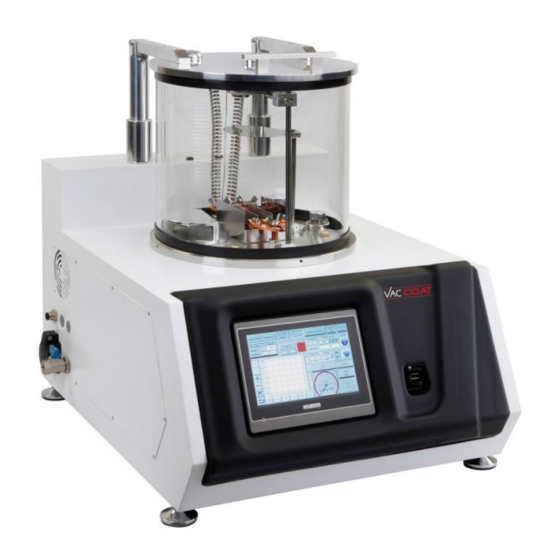
3. Introduction The Triple Source Thermal Evaporation Coater device; DTT; is a deposition system with thermal evaporation method in high vacuum, with glass cylindrical chamber and the turbo- molecular pump. This device by having a suitable size and its preferences is capable to reach the desired vacuum level in 10~15 minutes and depositing large group of materials, with the three thermal sources (boat- basket). -
Page 12: Mechanisms Of Sputtering Deposition Method
Mechanisms of thermal evaporation deposition method Thermal evaporation is a deposition method in a high vacuum condition with applying the electrical current to vaporize the source material and deposition on the substrate based on the pressure differentiation between the source and the sample holder. This method is one the most common... -
Page 13: Specifications
Specifications Table 2: DTT Desktop Triple Source Thermal Evaporator Coater Specification Dimension 650 Width x 500 Depth x 560 Height mm Weight 60 Kg Glass Chamber Dimension Pyrex Cylinder Shape, Diameter 300mm, Height 250mm, Thickness 7mm Display Screen 7” Diagonal (16:9) 800x480 High Color- Graphic TFT- LCD User Interface Color &... -
Page 14: Advantages
* CAUTION: Single phase AC power with appropriate earth connection is required. 3-2-1 Advantages 1- Easy operation and fast preparation of system for deposition. 2- Controlling the layer thickness with high repeatability during the deposition. 3- Easy insertion and removal of samples. 4- The possibility of using different materials for the thermal evaporation purpose. -
Page 15: The Equipment Inside The Metal Box
The electrical parts, electronic modules and turbo-molecular pump are inside the metal box. The diaphragm backing pump is outside the machine. 3-2-3 The equipment inside the metal box (Figure 3 Inside the metal box, there is a tray -3), including electrical and electronic parts of the device. -
Page 16: Figure 3 -4: Inside The Vacuum Chamber
1- Turbo inlet connection 2- 4 pin electrical feed through 3- Gas inlet 4- Pressure gauge connection 5- Copper electrode 6- Thickness gauge sensor 7- Rotational sample holder 8- Shutter 9- Air filter for the ventilation purpose Figure 3 -4: Inside the vacuum chamber Vaccoat Co. -
Page 17: Figure 3 -5: Copper Electrodes
To prevent the leakage, avoid any bumps or scrapes, especially in areas where the glass chamber is connected to base and Aluminum door. Hitting the edges of the glass will cause the leaks in that area. Copper Electrode This device is equipped to three separated copper electrodes to hold the boat for evaporation purpose. -
Page 18: Figure 3 -6: Feedthrough And Thickness Meter Cooling System (Plastic Blue Hoses)
It’srecommendedthatusetheBoatswiththicknessoflessthan0.1mmandwidthoflessthan8 If the deposition time is less than 15 minutes and the power supply current is less than 40 Amp, there is no need to cool the electric feedthroughs and so thickness meter. But for more time or currents, it’srecommendedtocoolfeedthroughs and thickness meter (Figure ... -
Page 19: Figure 3 -7: Electronic Shutter
iii. Shutter This device is equipped to an electronic shutter and its positioning can be controlled through the touch screen control panel. The distance between the shutter and the substrate and the thermal source is adjustable. For this purpose, the operator should opentheshutter’sconnectiontoshaft and tight it back after the height adjustment. -
Page 20: Figure 3 -9: Motorized Sample Holder
In order to use of sample rotation during the deposition process, set the samples on the rotational (Figure 3 surface and fix them by the clasps. Fix the surface on the right place -9) and connect the motor power cable. For setting the desired speed see the item No. 9 in part 5 -2. NOTE: Inordertoincreasethemotorlifetime,it’srecommendedthatturn on sample rotation motor after opening the shutter and after closing the shutter or finishing the deposition turn off it. -
Page 21: Figure 3 -10: Turbo Molecular Pump Inlet
Turbo-molecular pump inlet Due to the high speed of rotating vane pumps of turbo, (70 thousand RPM) entry of anything even very fine particles, will cause a serious damage to it, so in order to protect the pump, four filters is used by the following description: 1. -
Page 22: 5- Dc High Voltage Power Supply
Figure 3 -11: Pressure gauge inlet 3-2-5 High current power supply Following procedure indicates the current power supply usage for the thermal evaporation method: 1. Connect Common, high current and 24 V cables to the right place on the metal box.(see Figure ... -
Page 23: Figure 3 -12: High Current Power Supplies (Back View)
NOTE: After completion of the deposition, lower the current flow and wait for venting inside the chamber up to 15 minutes. The boat or basket is hot, and in the presence of oxygen will be oxidized. Figure 3 -12: High Current Power Supplies (Back view) Vaccoat Co. -
Page 24: 4- Set Up And Installation
4- Set up and Installation This device must have a single phase AC earth connection. The installation of this device must be done by expert and professional personnel and in accordance with these instructions. Failure to do so may result in damage of the machine. It is necessary for any user, who is going to work with this device, to attend the training course which will be held by Vaccoat company's experts and receive a license to operate. -
Page 25: The Connections
The accessory box and its content should match with DTT list. All parts of the devices should not include the loose and opened pieces especially chamber glass and L-shaped O-rings. The device must be delivered in vacuum condition. For venting the system, must open the blue valve on the side of the device. -
Page 26: Electric Connection
Figure 4 -1: Side view of the DTT 4-3-1 Electric Connection 1- The main cable Make sure the connections are firmly in place. The plug which device is connected must be properly earthed. This prevents the user from electrical shock, if any short circuit happens in the system. -
Page 27: Vacuum Pump Connection
Figure 4 -2: Back Side view of DTT 4-3-2 Vacuum pump connection (Figure 4 The backing vacuum pump connects to the device, by the hose with length of 1.5 m -1). 4-3-3 The Connection of cooling system thickness gauge To keep the quartz crystal cool during the deposition by a proper flow of water (about 0.5 liters per minute) passes through the thickness gauge... -
Page 28: Figure 4 -3: Water Filter For Installing In The Cooling System
Before start the water circulation, the leakage inspection must be done, especially for the hoses which reach the thickness gauge. This is because these parts are adjacent to boards and electronic components and pouring water might cause the short circuit or burn some of them. Figure ... -
Page 29: 5- Operation
5- Operation There are a number of adjustable parameters that the user can monitor and adjust through the touch screen control panel. List of adjustable parameters is shown in Table 5. Table 3: Adjustable Parameter in Touch Screen Parameter Allowable Range Tooling Factor 0.2~9.99 (Default Value is 1) Source Material... -
Page 30: Figure 5 -1: Main Switch Of The Backing Pump
Figure 5 -1: Main switch of the backing pump NOTE: It is recommended to use the boat or basket with the thickness in range of 0.05~0.1 mm. It makes the boat to reach the desired temperature with the lower current. ... -
Page 31: Sputtering Deposition Manual
Figure 5 -2: Power board Deposition Manual 8- Push the start button on screen. Figure 5 -3: Start Page (Figure 5 All the vacuum and deposition parameters are visible on the home Page -4). Vaccoat Co. | DTT Operating Manual... - Page 32 The home page contains two sections, commander items and display items. The commander items are as follows: - Vacuum pump activation - Turbo-molecular pump page - Target type and Thickness gauge setting page - MFC’ssetting - Motorized Part page or boat selection. Note that, once this page is open the other part of screen will not operate.
-
Page 33: Figure 5 -4: Main Page
Figure 5 -4: Main Page (Figure 5 9- Using the boat selection feature, place the substrate to the desired Source position -5). Use sample rotation to obtain a thin film with high uniformity. Figure 5 -5: Motorized page NOTE: Place a steel cube under the basket or boat to avoid the deposition of the base plat and make sure that is not in contact with the boat. - Page 34 10- Close the door. Once closing the door, be careful not to hit the glass. 11- Adjust the setting for target and the thickness sensors. The DTT, uses one crystal thickness sensors, measuring the thickness of layers deposited on the substrate.
-
Page 35: Figure 5 -6: Thickness Gauge Page
NOTE: If you are upgrading the software for first time, before to start the deposition press the Zero Thickness meter, otherwise it will not show the thickness. On the screen the crystal life option shows the remaining of its life. And before the end of its life the user should provide the new one. -
Page 36: Figure 5 -8: Turbo Molecular Pump Page
If the new target is not on the list, then users must use the Custom Key new material and enter the density in terms of gr / cm , and then press the OK. In the target selection window there is an option called Tooling Factor. This parameter is set based on the distance from the sample holder and so angle relative to the target. -
Page 37: Figure 5 -9: Pressure Display In The Main Page
In the absence of leaks, after 10 minutes the system pressure will reach 2 x10 and after 45 minutes it will reach 8x10 In the turbo pump page the pump’s status parameters are continuously monitored. If a parameter is outside of the permitted range of operation, it will turn to red. To view the allowable range of each parameter, refer to Appendix 1. -
Page 38: Figure 5 -10: Mfc (Mass Flow Control) Page
Figure 5 -10: MFC (Mass Flow Control) Page 15- Choose the deposition mode based on time or thickness. In this section, the user can adjust DTT setting for the mode of deposition according to his/her needs, based on the thickness of the active layer or the time. (Figure 5-9) If the thickness is not important for the user by setting the time, the thickness will be disabled automatically and the sputtering will be done on time and when the set time is reached, the device will stop sputtering. -
Page 39: Figure 5 -11: Deposition Mode Setting Section In Main Page
Figure 5 -11: Deposition mode setting section in main page 16- Allow the system to reach the pressure of 5x10 If you start the heating the boat in higher level of pressure the boat will oxidized. 17- Activate the HC key, which stands for High Current from on the touch screen control panel. 18- Rotate ON / OFF switch clockwise on the right of the power supply (Figure 3-13). -
Page 40: Figure 5 -12: Thickness And Pressure Curves Display
21- Turn the shutter around to start the deposition. By starting the deposition red /violet graph on the main screen will be displayed. Information on thickness, pressure and flow during the sputtering process, are visible as following. The Pressure – Thickness graph Figure ... -
Page 41: Figure 5 -13: The Logger Page
Figure 5 -13: The logger page In this sector the yellow line indicates the thickness and the green line indicates the pressure. Operation Converting the graph to data and vice versa Start to draw the graph Zoon in Zoom out Deleting the graph Undo key Vaccoat Co. -
Page 42: Picking Up The Sample
Operational Page Figure 5 -14: Operational page In this window deposition parameters are displayed in a new form, and the users who have no interest in graphs can use this sector. Picking up the Sample At the end of the deposition, and cutting off the water, and closing the main valve of the gas cylinder, to turn off the system as user should follow the below instruction: NOTE: After completion of the deposition, lower the current and wait for venting inside the chamber up... -
Page 43: Device Setting
close the ball valve and turn off the vacuum pump. Turn off the system by Turn Off key on the screen. 6- Disconnect the Power supply cable from the plug. Device Setting The main setting of the device should be done in the following page. Figure ... -
Page 44: Figure 5 -16: History Page
Shows the status of device. Status To save the setting and going on main page. Main Active and deactivate the beep sound Beep Sound History Page Figure 5 -16: History Page This window will allow the user to see date, time, and pressure the thickness of the last 300 layer which is deposited with the latter view. -
Page 45: Figure 5 -17: Maintenance Page
Maintenance page Figure 5 -17: Maintenance Page This system is designed for the quick troubleshooting and user normally do not need this sector. This sector contains 6 parts: Part I: Including the option of the sputtering system. If not it is not active, the light located under the each item turns to red and if it is enabled and having no defect is green. -
Page 46: Table 5: Ntc Section Parameters
The various part of devices in the field are displayed with the initials, therefore, T1, represents the thickness gauges, the letter P, represents the pressure, the letter m, indicating the motor, the letter r, represents the relay module inside metal boxes and F represents the mass flow controller (MFC). - Page 47 Choose the new file with the suffix of prp and press OK. Then the device will replace the new version with the old one. It is recommended to save the old version before upgrading. Make Zero Thickness only for first time after uploading the new software. Restart Panel AP: Turns on the device and opens the main page.
-
Page 48: Crystal Replacement
6- Maintenance Make sure the electricity power key is Turned off, during any part of maintenance activity. Table 6: The maintenance activities time and description. Activity Time After the deposition, once the inner layer of Cleaning the Chamber chamber is covered by the layers. Cleaning the particles inside the chamber When the parts are deposited by layers and it has scaling appears. -
Page 49: Figure 6 -1: Door Holder Screw
Figure 6 -1: Door holder screw 2- Remove the crystal placed on small grooves on the holder. Figure 6 -2: Small groove to replace the new crystal 3- Insert the new crystal with caution in the right direction to the groove shown in the Figure 6-3. -
Page 50: Cleaning The Device
Figure 6 -3: Insertion of new crystal to the groove 4- To avoid falling crystal, keep the crystal holder in such a way that the groove is side 5- Put the crystal holder in place in a way that the groove is side up. 6- Tighten the screws holding the door. -
Page 51: Transportation And Handling
To ensure the clearance of acid on the glass, clean it with a cloth soaked in acetone. Avoid any skin or eye contact while using acid. Avoiddevice’sbodycontactwithacetone.Itwilldamagethepainting of the body. O-rings First open the clips of O-rings, and then carefully remove them. It should be noted that it should not be stretch away because of its material (Viton) with low elasticity, and it will not return to its initial state. -
Page 52: Table 7: Troubleshooting Table Of Dtt
Troubleshooting the DTT This device does not need everyday service. But in case of any problem in accordance with Table 9, can troubleshoot and then fix it. Table 7: Troubleshooting table of DTT Item Reason Troubleshoot 1. By visual inspection to remove a 1. -
Page 53: Figure 6 -4: Connecting The Alternative Crystal To Test The Thickness Meter
First, with a visual inspection, make sure that there is no particle on the crystal. After ensuring the absence of such a problem, turn the golden socket which connects the thickness gauge wire to the crystal counter-clockwise to be removed. Then connect the test crystal (Figure 6-4) to the wire and wait for 10 seconds, if the crystal life turns to Green and showed the 98% or 99% that means there is a problems with connection of crystal three springs which pushing it upwards (Fig. -
Page 54: Figure 6 -5: Different Parts Of Thickness Gauge
Figure 6 -5: Different parts of thickness gauge Put back the crystal’swirein place, with an Allen wrench in loose the thickness gauge door a little bit and turn it about 30 degrees and push down. Then wait for 10~15 second and if the problem still there, open the crystal door slightly and be careful not to drop the crystal. - Page 55 Basically leaks are divided into two categories: Real and Virtual leaks. The real leaks are happened because of openings arise in a vacuum chamber. If the vacuum pump turned off the pressure is gradually increased and will be identical to the atmospheric pressure. The Virtual leaks that is not because of holes between the vacuum chamber and the atmosphere, but it has reasons such as trapped air in the vacuum chamber that the gradual release of it is not allowing the vacuum to reduce the pressure.
- Page 56 sensible will cause leakage but the sacks which are not possible to feel with nails are usually not important. In the presence of such sacks with very soft sandpaper (800 or 1000) sand the scratches to disappear, then clean location with a clean cloth and some alcohol. Vaccoat Co.
- Page 57 7- Appendix 1 Turbo Molecular pump parameter list: Designation Min. Max. Default Unit Format Description Actual frequency 6553 Actual rotor frequency ˚C Actual motor tempreture ˚C Actual converter tempratture ˚C Motor temperature Exceeding motor temperature warning threshold warning threshold results in a warning Setpoint frequency 1000 Setpoint of the rotor frequency...
Need help?
Do you have a question about the VAC COAT DTT and is the answer not in the manual?
Questions and answers