Advertisement
Quick Links
Advertisement

Related Manuals for Taiga Concept LOHKO BOX 3


Summary of Contents for Taiga Concept LOHKO BOX 3
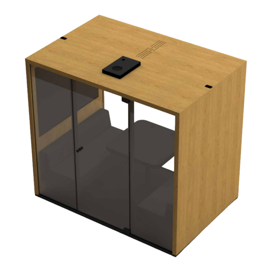
- Page 1 ASSEMBLY GUIDE LOHKO BOX 3 4,5h...
- Page 2 If you find damage, document with photos according instructions Check if there is any damage Remove top cover and check that Carry the elements Assemble the product to the package there are no signs of damage before Note: Take extra care unpacking.
- Page 3 1. Take images where you can see 2. Take closer images of the damage 3. Contact your local Taiga dealer full package from 2 different angles which show the damage 1. Take images where you can see 3. Contact your local Taiga dealer 2.
-
Page 4: Installation
Concept or Taiga Concept local dealers. will break easily. It is recommended to use Taiga Concept local When assembling the product make sure you Choosing location dealers authorized assembling person. -
Page 5: Elements & Components
Elements & Components 1x CD004 1x CR004 1x CF004 1x CD005 2x CD006 1x CR005 1x CF005 2x SR006 1x SR005 1x CG003 1x SR007 1x CW010 2x CG004 1x CW007 1x EP106 1x CW008 3x CG005 500cm 1x EC1xx 2x CA2xx 1x CW009 100cm... - Page 6 Elements & Components Equipments & tools Roof 4x SC006 2x SR001 4x SS002 Gloves Safety glasses Safety shoes Safety helmet Doorframe & acoustic panel Roof 4x SS003 12x SC001 16x SC002 2x SS004 Wall connector Hinges Screw machine + bits Hex key set Spirit or laser level plate...
- Page 7 ATTENTION Never put glass against hard surface, use always carton or carpet under the glass. Use always 2 person and suction cups to lift glass...
- Page 8 Note: If LB TABLE is installed, SR005 is not needed SR005 SR003 CF005 CF004 Make sure the floor elements are in the final position Do not slide the product over the room floor...
- Page 9 Hex key 4mm NOTE: Do not continue before floor is level SC006...
- Page 10 SR003...
- Page 11 Keep the wall upright until the glass element is added. CW010...
- Page 12 Add seal 2/3 of the length SS002 CG005 If back glass is close to a wall, clean it before placing Never put glass against a hard surface, always use carton or carpet under the glass. Always use 2 persons and the suction cups to lift glass...
- Page 13 Keep the wall upright until the glass element is added. CW009...
- Page 14 Add seal 2/3 of the length SS002 CG005 If back glass is close to a wall, clean it before placing Never put glass against a hard surface, always use carton or carpet under the glass. Always use 2 persons and the suction cups to lift glass...
- Page 15 SR006...
- Page 16 If power is supplied from floor level, connect supply cable (EC1xx) to the connector inside the wall before installing the wall In case power is supplied from CW007 the ceiling, check page 52 Cable for table is routed through the groove inside the booth...
- Page 17 SR006...
- Page 18 CW008...
- Page 19 SF006 Warning: Do not apply excessive force SR003 SC003 Make sure the walls lines perfectly on top and that there is no gap bottom of the wall and oor joint...
- Page 20 CR005 Do not scratch the element surfaces and be careful with sharp edges...
- Page 22 SR007...
- Page 23 CR004...
- Page 24 5 mm Cables from the roof element need to be connected with the cables from the wall element. Push all the connectors and cable inside the elements.
- Page 25 Before screwing, make sure the elements are in place SC001...
- Page 26 EP109 this side pointing up...
- Page 27 780 mm SS005 Install the seals (SS005) to the edges of the glass to make the joint soundproof and protect the glass.
- Page 28 CG005 If back glass is close to wall clean glass before placing it Never put glass against a hard surface, always use carton or carpet under the glass. Always use 2 persons and the suction cups to lift glass...
- Page 29 Lift the glass inside the grooving of roof element and slide it then to the grooving of the oor element.
- Page 30 Make sure the booth is upright Make sure the middle glass is centered and there are no gaps...
- Page 31 SS004...
- Page 32 CG004 CG004 Never put glass against a hard surface, always use carton or carpet under the glass. Always use 2 persons and the suction cups to lift glass...
- Page 33 SC002 CD006 Note: even small gap may lead to sound leakage...
- Page 34 Note: instructions for a right handed hinge. Route the cable through the groove and hole For a left handed hinge, route the cable on the opposite side. CD006...
- Page 35 Note: even small gap may lead to sound leakage Make sure the cable will stay inside the grooving SC002...
- Page 36 SS003 Pay extra attention to the positioning of the glass elements ~2 mm ~2 mm CONTROL PANEL SIDE HINGE SIDE ~2 mm ~2 mm...
- Page 37 CD005 Installing hadle side door frame.
- Page 38 Magnets on the control panel connect to the screwheads EP106 Plug and test electricity See page 52 option 1 or 2...
- Page 39 CD004 Remove the tape cover...
- Page 40 Follow the instruction carefully, once the frame attach the tape it can not be removed. Doorframe 91 cm Doorframe Glass Glass Start pushing the door frame against the tape on glass from the bottom and move slowly toward the top. Make sure the glass will be attached to the tape as shown in the picture.
- Page 41 SC004 SR001...
- Page 42 Carpet is oversized from three side and need to be cut to meet the edges. SCA003 When installing the carpet, use tape on the center and the edges...
- Page 43 CG003 Clean around these areas and dry before assembling hinges Never put glass against a hard surface, always use carton or carpet under the glass. Always use 2 persons and the suction cups to lift glass...
- Page 44 Torque = 20 Nm BOTTOM BOTTOM Make sure the glass does not go over the hinge from the top. This will protect the glass from the metal part to hit when swinging. Never use drilling machine to tighten hinge screws...
- Page 46 Make sure the up corner does not damage the elements SC005 > 20 ° Use three washers rst and add or remove if needed to adjust the door. Make sure that door glass will not touch hinge support parts while and after assembling the door...
- Page 47 Warning! Make sure the screws don’t damage the glass SC005 SC005 > 130 °...
- Page 48 SF003 ~3 mm SF001 ~3 mm...
- Page 49 Screws for acoustic panels SC002...
- Page 50 CA2xx...
- Page 51 Increase magnetic strength by adding Make sure the door closes properly. magnets on the metallic strip (no screws required) Test if the door stays closed on maximum ventilation SM001...
- Page 52 Option 2: Powercord assembled from roof level...
- Page 53 ll the holes with piece of rubber seal SS002 Clean all surfaces Make sure that any water used in the cleaning process Turn on the ventilation, check each side and corner of the door by hand that there is no air leaks will not leak between the Check if there is any air leak between frames and elements/glasses.
- Page 54 Your Natural Workspace...
- Page 56 www.taigaconcept.fi Assembly support +358 40 138 4302...
Need help?
Do you have a question about the LOHKO BOX 3 and is the answer not in the manual?
Questions and answers