Table of Contents
Advertisement
Quick Links
Operating and installation
instructions
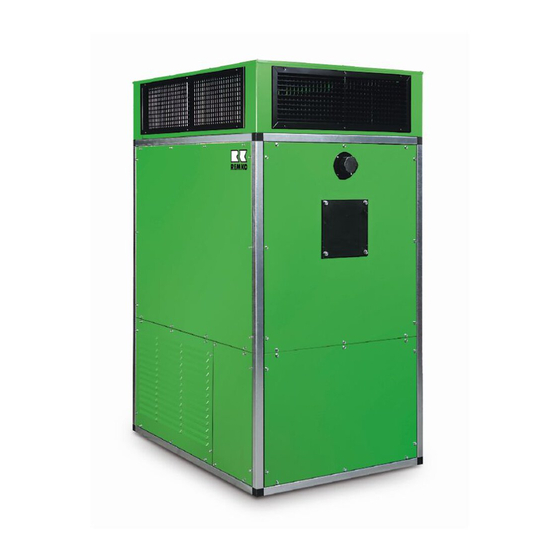
REMKO VRS EN series
Universal heating units for oil and gas firing
VRS 25 EN, VRS 50 EN, VRS 75 EN, VRS 100 EN, VRS 130 EN, VRS 170 EN,
VRS 200 EN, VRS 270 EN, VRS 340 EN, VRS 440 EN, VRS 540 EN
Edition EN - X04
Read the instructions prior to performing any task!
Advertisement
Table of Contents

Related Manuals for REMKO VRS EN Series

Summary of Contents for REMKO VRS EN Series
- Page 1 Operating and installation instructions REMKO VRS EN series Universal heating units for oil and gas firing VRS 25 EN, VRS 50 EN, VRS 75 EN, VRS 100 EN, VRS 130 EN, VRS 170 EN, VRS 200 EN, VRS 270 EN, VRS 340 EN, VRS 440 EN, VRS 540 EN...
-
Page 3: Table Of Contents
Content Safety notes Unit description 5 - 7 8 - 11 Installation instructions Exhaust gas ducting 11 - 12 13 - 14 Installation and assembly Commissioning 15 - 16 Shutdown Care and maintenance 17 - 18 19 - 20 Troubleshooting Maintenance protocol Intended use Customer service and guarantee... -
Page 4: Safety Notes
REMKO VRS EN Series Safety notes Always observe the respective local building code and fire prevention guidelines as well as the guidelines of the accident prevention and insurance associations when using the units. The units have been subjected The fastening must take place Portable fuel containers must ■... -
Page 5: Unit Description
Unit description The units are stationary, directly The robust construction and Locations at which units are fired fan-assisted heaters (WLE) careful processing of the units, used with heat exchanger and exhaust which are made exclusively of gas connection. high-quality materials, guarantee As directly fired fan-assisted The units can be directly fired with many years of trouble-free... - Page 6 REMKO VRS EN Series Mode of operation After switching off the units via After connecting the unit to the mains, the phase indicator lamp the heater selector switch or the H1 on the control box illuminates. room thermostats, the supply air...
- Page 7 Safety devices may not be When replacing the controller conditions of the unit should bypassed or disabled during unit, only an original REMKO be checked before resetting unit operation! spare part may be used! the STB.
-
Page 8: Installation Instructions
REMKO VRS EN Series Installation instructions With the installation of the units, Combustion air supply CAUTION the local and country-specific Overpressure and underpressure regulations (LBO) and combustion Sufficient supply of combustion in the installation area plant order (FeuVO) of the... - Page 9 if the units are installed in Set-up rooms that have an opening or pipe leading into the open air. The units must then only be The equipment must be ■ ■ The cross-section of the installed and operated in areas installed in such a way that it opening must be at least where the units can be supplied...
- Page 10 REMKO VRS EN Series Mounting on the ground If auxiliary equipment is The lines must be laid in such a ■ required for monitoring, way that they can be easily bled and are protected against corrosion The units must be set down stably maintenance and repair work, and mechanical damage.
-
Page 11: Exhaust Gas Ducting
Exhaust gas ducting Annual inspection and As a rule, the units must be Exhaust systems must be ■ maintenance connected to a suitable and type- dimensioned in terms of clear approved exhaust gas system. cross-section and height in such In accordance with the operating a way that the exhaust gases NOTE conditions, the units must, if... - Page 12 REMKO VRS EN Series Application examples: Example upright unit installation REMKO ASD exhaust system Stainless steel, double-walled, outdoor mounting REMKO ASE exhaust system Stainless steel, single-walled, indoor mounting The exhaust gas system 8 / 9 components are connected very simply through mating, and are secured with clamps.
-
Page 13: Installation And Assembly
Installation and assembly When installing the units, Room thermostat connection NOTE the regulations and ordinances The air intake may only take applicable to the respective federal The room thermostat (accessory) place via the intake openings state must always be observed. must be placed in a convenient provided. - Page 14 REMKO VRS EN Series A room thermostat or a day/night The combustion chamber must Gas connection ■ temperature control is connected not be underloaded (increased to the corresponding terminal condensate formation) Adequate gas pressure and block X2 in the control box for quantity of gas, in accordance these versions.
-
Page 15: Commissioning
Commissioning Commissioning the fan motor Motor thermal cut-out (TMC) Initial commissioning Testing the drive To protect the fan motor, a The initial commissioning of thermal cut-out is installed in the units and their forced-air 1. Check the fastening screws the motor winding. If too much burners must be carried out by of the entire drive are firmly heat is generated inside the motor,... -
Page 16: Shutdown
REMKO VRS EN Series The burner must be set to Heating mode Ventilation ■ optimum values in accordance with the manufacturer's The units operate fully 1. Turn the "Ventilate" selector specifications, but at least to automatically and in accordance switch. -
Page 17: Care And Maintenance
Care and maintenance For reasons of operational The restrictions on exhaust gas Soot deposits ■ readiness, functional safety, losses per §1 paragraph 1 of economic efficiency and compliance the ordinance on small furnace Even small deposits of soot on with emission limits, the operator systems (1st. - Page 18 REMKO VRS EN Series Cleaning the combustion chamber and heat exchanger 1. Disconnect the unit from 10. The combustion residues in 12. Ensure that the exchanger the power supply. the combustion chamber must tubes are correctly seated also be removed through the...
-
Page 19: Troubleshooting
Troubleshooting The unit does not start The burner does not start CAUTION If the burner should carry out Check the customer-provided Check the oil filter(s) for ■ ■ a fault shut-down once again mains power supply contamination. Replace after the start phase, then contaminated oil filter(s) another reset should be carried Check the fuses in the switching... - Page 20 REMKO VRS EN Series The supply air fan does not Possible causes of malfunction: NOTE start If all of the functional checks The units were not able to cool ■ have been carried out without Move the "Ventilate" selector down because the electrical any findings, please contact an switch to the "II"...
-
Page 21: Maintenance Protocol
✍ Maintenance protocol Unit type: ........ Unit number: ........10 11 12 13 14 15 16 17 18 19 20 Unit cleaned - outside - Unit cleaned - inside - Fan blades cleaned V-belt tension checked V-belt replaced Combustion chamber cleaned Heat exchanger cleaned Exhaust gas suppressors replaced Inspection cover seals replaced... -
Page 22: Intended Use
REMKO VRS EN Series Environmental Intended use Customer service and protection and guarantee recycling The units are designed exclusively As a prerequisite for any guarantee Disposal of packaging for heating and ventilation claims to be considered, it is purposes in industrial or... -
Page 23: Electrical Wiring Diagram
Electrical wiring diagram YΔ Optional Optional Lüften Ventilation YΔ Heizen Heating grün grün green green grün green 01 02 03 29 30 13 12 L1 L2 L3 N PE TW 1 TW 2 L1 N T1 T2 S3 B4 PE T8 T7 T6 B5 Regler-Einheit Wielandstecker... -
Page 24: View Of The Unit
REMKO VRS EN Series Exploded view of the VRS 25 EN - 200 EN unit Fig. VRS 50 E - standard version Fig. Fan with belt drive Replacement for item 6 from size 130 to 200 33 32 We reserve the right to modify the dimensions and design as part of the ongoing technical development process. -
Page 25: Spare Parts List
Spare parts list VRS 25 VRS 50 VRS 75 VRS 100 VRS 130 VRS 170 VRS 200 No. Designation EDP no. EDP no. EDP no. EDP no. EDP no. EDP no. EDP no. 2 Insulated cladding panel 1103210 1103211 1103212 1103213 1103214 1103215... -
Page 26: Unit Specifications
REMKO VRS EN Series Unit specifications - upright HB 90 VRS 50 EN - upright We reserve the right to modify the dimensions and design as part of the ongoing technical development process. - Page 27 Unit specifications - horizontal HB 90 VRS 50 EN - horizontal / left Legend: = Blank panel Pos. I – III = Blank panel Pos. IV = Burner box = Dust filter 3-sided, for free suction = Dust filter for duct connection = 3 or 4-sided exhaust hood = Intake guard Pos IV = Louvred intake panel Pos.
-
Page 28: Unit Dimensions
1050 1050 1100 1230 1330 1330 1090 1090 1535 1535 Dimensions D/E/K and G only refer to REMKO intake and exhaust accessories. We reserve the right to modify the dimensions and design as part of the ongoing technical development process. -
Page 29: Accessories
Accessories For direct exhaust to 2, 3 or 4 sides with built-in air directing louvres. Exhaust hood type HG All louvres are individually adjustable both horizontally and vertically. Dimen- sions 25 EN 50 EN 75 EN 100 EN 130 EN 170 EN 200 EN 270 EN... - Page 30 REMKO VRS EN Series Accessories U-profile design for the fastening of upright or horizontal units to the wall. Wall bracket type KN Fastening only to walls at least 24 cm thick (check statics). End-to-end M16 threaded pins with profiled steel on the underside should ideally be used (customer-provided fastening material).
- Page 31 Accessories Duct filters with easily replaceable plug-in filters with filter class G3. Dust filter type FK Additional filter classes are also available on request. for duct intake Any potentially remaining intake openings are to be closed with corresponding blank panels. Dimen- sions 25 EN...
-
Page 32: Technical Data
REMKO VRS EN Series Technical data Series Symbol Unit 25 EN 50 EN 75 EN 100 EN 130 EN 170 EN 200 EN 270 EN 340 EN 440 EN 540 EN Q ̇ Nominal heat load Nominal heat capacity 27.8 46.9... - Page 33 Max. intake temperature 40°C / max. exhaust temperature 100°C Gross calorific values H in standard condition: EL heating oil 12.61 kWh/kg Natural gas H 11.48 kWh/m Natural gas L 9.75 kWh/m Propane gas 28.14 kWh/m Propane gas 14.00 kWh/kg Additional specifications for fresh air and flue gas ducting The following applies to all models in the VRS EN range: -air heater: -air heater:...
-
Page 34: Drive Technical Data
REMKO VRS EN Series Drive technical data Electric motor(s) Fan(s) V-belt pulleys Rated pressure Electrical Power Nominal Nominal Sound Type Version Speed Version Motor - external connection consumption flow speed pressurelevel VRS EN mm Ø mm Ø dB(A) 230/1~ 0.55 6.80... - Page 36 REMKO QUALITY WITH SYSTEMS Air-Conditioning | Heating | New Energies Telephone +49 (0) 5232 606-0 REMKO GmbH & Co. KG Hotline within Germany Telefax +49 (0) 5232 606-260 +49 (0) 52 32 6 06-0 Klima- und Wärmetechnik Im Seelenkamp 12 E-mail info@remko.de...
Need help?
Do you have a question about the VRS EN Series and is the answer not in the manual?
Questions and answers