Table of Contents
Advertisement
Quick Links
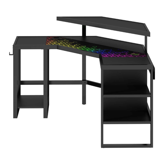
Leet Corner Gaming Desk
ADULT ASSEMBLY REQUIRED DUE TO THE PRESENCE OF SMALL PARTS, SHARP
POINTS, SHARP EDGES AS RECEIVED
If you have any questions regarding assembly or if parts are missing, DO NOT return this item to the
store where it was purchased. Please call our toll-free customer service number and have your
instructions and parts list ready to provide the model name, part name or factory number:
Pacific Standard Time: 8:30 a.m. - 4:30 p.m., Monday - Friday
Or visit our web site 24 hours a day, 7 days a week for product assistance at
THIS INSTRUCTION BOOKLET CONTAINS IMPORTANT SAFETY INFORMATION.
Model # SPLS-LTCGD
1-866-942-5362
www.whalenfurniture.com
Or e-mail your request to parts@whalenfurniture.com
PLEASE READ AND KEEP FOR FUTURE REFERENCE.
Date 2021-03-02
LOT NUMBER:
DATE PURCHASED: /
Rev. 0001-A
/
Advertisement
Table of Contents

Related Manuals for Whalen LEVELUP SPLS-LTCGD


Summary of Contents for Whalen LEVELUP SPLS-LTCGD
- Page 1 LOT NUMBER: DATE PURCHASED: / Leet Corner Gaming Desk Model # SPLS-LTCGD ADULT ASSEMBLY REQUIRED DUE TO THE PRESENCE OF SMALL PARTS, SHARP POINTS, SHARP EDGES AS RECEIVED If you have any questions regarding assembly or if parts are missing, DO NOT return this item to the store where it was purchased.
- Page 2 M A X I M U M R E C O M M E N D E D W E I G H T L O A D S MANUFACTURER: Whalen Furniture Manufacturing CATALOG: Leet Corner Gaming Desk MODEL # SPLS-LTCGD MAXIMUM LOAD 50 lb.
- Page 3 Low Voltage Lighting Systems User Guide Please read this user guide before installing and using your Low Voltage Lighting Systems 1.THE COMPONENTS LIST 5VDC 2.0A Connect to wireless charger 1> Class 2 power supply----1pc; 2> RF control---1pc; 3> LED control box---1pc; Connect to power supply 4>...
- Page 4 Operation 1.Using Remote Controller Please pull out the battery insulate tape before using. The RF wireless remote signal can pass through barrier, so it’s not necessary to aim at the main unit when operating. For proper receiving remote signal, please do not install the main unit in closed metal parts.
- Page 5 Wireless charger operation manual First of all, thanks sincerely for buying this product. For your safely, please read this manual carefully before using this product. The first: To protect people from harm and property loss, we make a clear explanation on what you do should obey: A.
- Page 6 The second: Product advantages 1) The product is of high sensitivity, intelligent recognition, put a charge; After charging, automatically enter standby mode of the product; 2) Charge for all QI compliant product; 3) Efficiency can reach more than 70%, less heat; 4) In the process of charging can be free to pick up, answer the phone, freeing discharge or charge;...
- Page 7 Installing the battery The battery is supplied with the remote control. The first thing to do with the remote control is to remove the plastic sheet insulated the battery. For replacement battery, use lithium-based CR2025 battery. Please follow the sequence below to replace the battery.
- Page 8 Parts and Hardware List Please read completely through the instructions and verify that all listed parts and hardware are present before beginning assembly. A- Left Top Frame (Qty. 1) B- Corner Top Frame (Qty. 1) C- Right Top Frame (Qty. 1) D- Left Outer Frame (Qty.
- Page 9 Parts and Hardware List Please read completely through the instructions and verify that all listed parts and hardware are present before beginning assembly. MODE SPEED DEMO SPEED COLOR MODE BRIGHT COLOR BRIGHT RF Wireless Y- Plug of Light Fixture with Remote Control and Battery (Qty.
- Page 10 Left Side Desk Assembling NOTE: Please do not fully tighten all bolts until you finish assembling all parts. Once assembled, go back and fully tighten all bolts. This will make the assembly easier. 1. Unpack the unit and confirm that you have all the hardware and required parts. Assemble the unit on a carpeted floor or the empty carton to avoid any scratch.
- Page 11 Left Side Desk Assembling 4. Using the pilot holes as a guide, fasten the Left Bottom Panel (V) to the Left Frames (D and E) with four 12 mm Screws (11). 5. Stand the assembled unit upright. 6. Attach the Left Back Short Stretcher (H) to the Left Frames (D and E) with two 12 mm Bolts (1) and two Washers (4 and 5).
- Page 12 Left Side Desk Assembling 7. Attach the Left Back Long Stretcher (I) to the Left Middle Frame (E) with one 12 mm Bolt (1) and the Washers (4 and 5). 8. Attach the Corner Left Post (L) to the Left Top Frame (A) and the Left Back Long Stretcher (I) with three 32 mm Bolts (3) and three Washers (4 and 5).
- Page 13 Right Side Desk Assembling 9. Securely screw the Cam Bolts (9) into the designated small holes on the Right Top Frame (C) with a Phillips screwdriver. DO NOT overtighten the Cam Bolts. NOTE: Screw-in cam bolts must be screwed down flush. 10.
- Page 14 Right Side Desk Assembling 11. Attach the Right Side Frame (F) to the Right Top Frame (C) with two 32 mm Bolts (3) and two Washers (4 and 5). 12. Attach the Right Inner Panel (W) to the Right Top Frame (C) by engaging the Cam Locks (7). (Refer to page 3 on Cam Lock system operation supplement).
- Page 15 Right Side Desk Assembling 13. Attach two Right Shelves (X) to the Right Inner Panel (W) by engaging four Cam Locks (7) and four 30 mm Wood Dowels (10). (Refer to page 3 on Cam Lock system operation supplement). 14. Secure the Right Shelves (X) to the rails of the Right Side Frame (F) with four 25 mm Screws (12).
- Page 16 Right Side Desk Assembling 15. Stand the assembled unit upright. 16. Attach the Corner Right Post (M) to the Right Top Frame (C) with two 32 mm Bolts (3) and two Washers (4 and 5). 17. Fasten the Right Back Stretcher (K) to the Corner Right Post (M) with the 32 mm Bolt (3) and the Washers (4 and 5).
- Page 17 Corner Assembling 19. Fit the Corner Top Frame (B) onto the U-shaped brackets on the Top Frames (A and C) and fasten them into place with four 12 mm Bolts (1). 5 4 2 20. Fasten the Corner Top Frame (B) to the Top Frames (A and C) with four 25 mm Bolts (2) and four Washers (4 and 5).
- Page 18 Corner Assembling 21. Attach the Middle Back Stretcher (J) to the Left and Right Posts (L and M) with two 12 mm Bolts (1) and two Washers (4 and 5). 22. Position the Corner Top Panels (T and U) onto the top of the assembled unit.
- Page 19 Corner Assembling 23. Fasten the Corner Top Panels (T and U) to the rails of Top Frames (A and C) with six 25 mm Screws (12). 24. Secure the Corner Top Panels (T and U) to the metal tabs with eight 12 mm Screws (11). 25.
- Page 20 Corner Assembling 26. Using the pilot holes as a guide, Attach two Cord Clips (14) to the Top Panels (T and U) with two 12 mm Screws (11) in each. 27. Attach the Hutch Top (G) to the Left and Right Posts (L and M) with four 12 mm Bolts (1) and four Washers (4 and 5).
- Page 21 Assembly Instructions 28. Fasten the Left Cord Management (N) to the Left Side assembly with five 12 mm Bolts (1). 29. Secure the Right Cord Management (O) to the Right Side assembly with five 12 mm Bolts (1). 30. Attach the Middle Cord Management (P) to the Left and Right Posts (L and M) with four 12 mm Bolts (1).
- Page 22 Assembly Instructions 31. Attach the Light Support (Q) to the Middle Cord Management (P) with two 12 mm Bolts (1) and two Hex Nuts (6). Note: Ensuring that the light function properly. This can be done by moving the Light Support (Q) forward and back.
- Page 23 Assembly Instructions 33. Clip the LED light bar into the buckles (Y). 34. Feed the wire of Wireless Charger (Z) through the cutout of the Desk Top and push into the cutout from top of Desk Top ensuring the wire are not pinched. NOTE: You can use the Cord Clips to help keep your entertainment center’s cables and cords organized.
- Page 24 Assembly Instructions 35. Connect the plug of the Light Fixture together properly. Secure the cord in place with plastic ties. Make sure the loose connecting wire is taped securely and out of the way. Connect the light fixture to the power transformer.
- Page 25 Assembly Instructions 36. Position the Corner Mouse Pad (S) onto the Corner Front Top Panel (T). 37. Attach the Accessory Hook (R) to the Left Top Frame (A) with two 12 mm Bolts (1). Wireless Charger Floor leveler 38. Position the unit at the desired location against a wall. If necessary, adjust the Floor Levelers at the bottom of the frames to level the unit.
- Page 26 Should this product be defective in workmanship or materials or fail under normal use, we will repair or replace it for up to one (1) year from date of purchase. Every Whalen Furniture product is designed to meet your highest expectations. We guarantee that you will immediately see the value of our fine furniture.
Need help?
Do you have a question about the LEVELUP SPLS-LTCGD and is the answer not in the manual?
Questions and answers