Moxa Technologies UC-8100 Series Quick Installation Manual
Hide thumbs
Also See for UC-8100 Series:
- Hardware user manual (19 pages) ,
- Quick installation manual (2 pages)

Related Manuals for Moxa Technologies UC-8100 Series


Summary of Contents for Moxa Technologies UC-8100 Series
- Page 1 UC-8100 Series Quick Installation Guide Version 4.1, January 2021 Technical Support Contact Information www.moxa.com/support 2021 Moxa Inc. All rights reserved. P/N: 1802081000014 *1802081000014*...
-
Page 2: Package Checklist
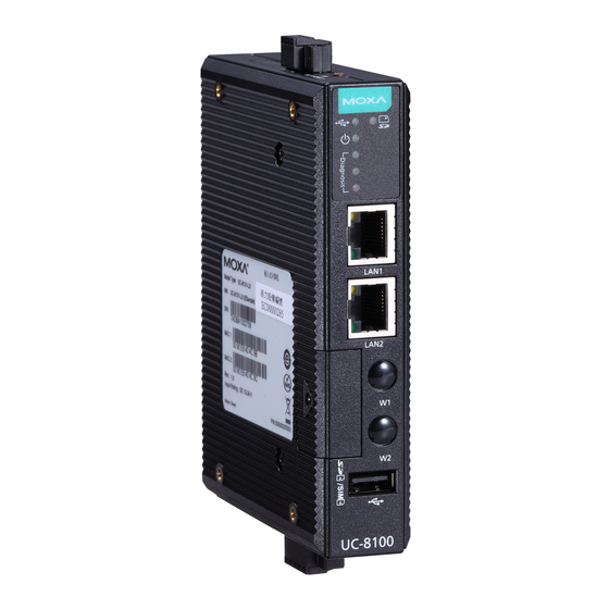
Overview The UC-8100 computing platform is designed for embedded data-acquisition applications. The computer comes with one or two RS-232/422/485 serial ports and dual 10/100 Mbps Ethernet LAN ports, as well as a Mini PCIe socket to support cellular modules. These versatile communication capabilities let users efficiently adapt the UC-8100 to a variety of complex communication solutions. - Page 3 3 (Green + Yellow + Red): Excellent 2 (Yellow + Red): Good 1 (Red): Poor Wireless module is not detected Diagnosis Green These 3 LEDs are used for diagnostics Yellow and are programmable. For additional details, refer to the UC-8100 Series Hardware Manual. - 3 -...
-
Page 4: Connector Description
Installing the UC-8100 There are two sliders on the back of the unit for DIN-rail and wall mounting. Mounting on a DIN Rail Pull out the bottom slider, latch the unit onto the DIN rail, and push the slider back in. Mounting on a Wall Pull out both the top and bottom sliders, align the screws with the... - Page 5 Grounding the UC-8100 Grounding and wire routing help limit the effects of noise due to electromagnetic interference (EMI). The shielded ground (sometimes called protected ground) contact is the top contact of the 3-pin power terminal block connector when viewed from the angle shown here.
- Page 6 Console Port The console port is a RS-232 port that can be connected with a 4-pin pin header cable. You may use this port for debugging or firmware upgrade. Signal The USB 2.0 port is located at the lower part of the front panel, and supports a USB storage device driver.
- Page 7 Follow these steps to install the cellular module. 1. Unfasten the screws on the side panel of the computer and remove the cover. 2. Find the location of the PCIe socket. 3. Remove the plastic plate and the sticker on both sides of the large thermal pad and place it in the socket.
- Page 8 5. Remove the plastic plate and the sticker on both side of the small thermal pad and stick the thermal pad on to the module. 6. Install the antenna cables. There are three antenna connectors on the module; two for cellular antennas and one for a GPS antenna.
- Page 9 10. Connect the antenna to the antenna connector. 11. Replace the cover of the computer. Connecting the UC-8100 to a PC Through the serial console port with the following settings: Baudrate=115200 bps, Parity=None, Data bits=8, Stop bits =1, Flow Control=None ATTENTION Remember to choose the “VT100”...
Need help?
Do you have a question about the UC-8100 Series and is the answer not in the manual?
Questions and answers