GORMAN-RUPP PUMPS D Series Installation, Operation, And Maintenance Manual With Parts List
Hide thumbs
Also See for D Series:

Related Manuals for GORMAN-RUPP PUMPS D Series


Summary of Contents for GORMAN-RUPP PUMPS D Series
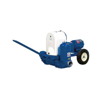
- Page 1 OM-01490-04 June 17, 1987 Rev. F 07‐05‐19 INSTALLATION, OPERATION, AND MAINTENANCE MANUAL WITH PARTS LIST D SERIES PUMP MODEL 3D-B GORMAN‐RUPP PUMPS www.grpumps.com 1987 Gorman‐Rupp Pumps Printed in U.S.A.
- Page 2 Register your new Gorman‐Rupp pump online at www.grpumps.com Valid serial number and e‐mail address required. RECORD YOUR PUMP MODEL AND SERIAL NUMBER Please record your pump model and serial number in the spaces provided below. Your Gorman‐Rupp distributor needs this information when you require parts or service. Pump Model: Serial Number:...
-
Page 3: Table Of Contents
TABLE OF CONTENTS INTRODUCTION ........... PAGE I - 1 SAFETY ‐... - Page 4 TABLE OF CONTENTS (continued) PUMP AND GEARBOX DISASSEMBLY AND REASSEMBLY ..... . . PAGE E - 10 Suction And Discharge Check Valve Removal .
-
Page 5: Introduction
This is a D Series, positive displacement pump util izing a single‐action diaphragm to produce a straight‐through flow of liquid. The pump is ideally... -
Page 6: Safety- Section A
D SERIES OM-01490 SAFETY‐ SECTION A This information appllies to D Series ba sic diaphragm pumps. Gorman‐Rupp has no control over or particular knowl edge of the power source which will be After the pump has been installed, block used. Refer to the manual accompany... - Page 7 OM-01490 D SERIES drive components. It is strongly recom mended that unless absolutely necessary, no positive shut‐off valve be installed in the suction line; excessive restriction will Never install a positive shut‐off valve in the cause incomplete filling of the diaphragm discharge line;...
-
Page 8: Installation - Section B
D SERIES OM-01490 INSTALLATION - SECTION B Review all SAFETY information in Section A. For further assistance, contact your Gorman‐Rupp distributor or the Gorman‐Rupp Company. Since pump installations are seldom identical, this Pump Dimensions section offers only general recommendations and practices required to inspect, position, and ar... -
Page 9: Positioning Pump
OM-01490 D SERIES If the maximum shelf life has been exceeded, or if and move the unit are improperly wrapped anything appears to be abnormal, contact your around the pump. Gorman‐Rupp distributor or the factory to deter mine the repair or updating policy. Do not put the... -
Page 10: Fixed, Rigid Piping
D SERIES OM-01490 Fixed, Rigid Piping If the pump is mounted in a system with fixed, rigid piping, it is recommended that a flexible connec tion be installed at or near the suction and dis This pump is equipped with an integral suction ac... -
Page 11: Suction Lines
OM-01490 D SERIES of solids larger than the solids handling capability SUCTION LINES of the pump. To avoid air pockets which could affect pump prim This pump is designed to handle up to 2‐1/4 inch ing, the suction line must be as short and direct as (57,2 mm) diameter spherical solids. -
Page 12: Alignment
D SERIES OM-01490 To check parallel adjustment, lay a straightedge mended that unless absolutely necessary, across both coupling halves at the top, bottom and no positive shut‐off valve be installed in the sides. The horizontal parallel adjustment is correct suction line; excessive restriction will... -
Page 13: Operation - Section C
OM-01490 D SERIES OPERATION - SECTION C Review all SAFETY information in Section A. valve should be installed in the discharge line. Follow the instructions on all tags, labels and decals attached to the pump. STARTING Consult the operations manual furnished with the motor before starting the pump. -
Page 14: Priming
OM-01490 D SERIES If the pump will be idle for more than a few hours, or a gearbox with A 30:36:1 ratio and a 1750 if it has been pumping liquids containing a large RPM maximum input drive. Make certain amount of solids, flush it with clean water. -
Page 15: Troubleshooting - Section D
D SERIES OM-01490 TROUBLESHOOTING - SECTION D Review all SAFETY information in Section A. Before attempting to open or service the pump: 1. Familiarize yourself with this manual. 2. Shut off incoming power to the motor and lock it out to ensure that the pump will remain inoperative. - Page 16 OM-01490 D SERIES TROUBLE POSSIBLE CAUSE PROBABLE REMEDY PUMP REQUIRES Liquid solution too thick. Dilute if possible. TOO MUCH POWER Integral discharge check valve clogged Clean valve. or binding. Bearings in motor or gearbox Check bearings. worn or binding. PUMP...
-
Page 17: Pump Maintenance And Repair - Section E
D SERIES OM-01490 PUMP MAINTENANCE AND REPAIR ‐ SECTION E MAINTENANCE AND REPAIR OF THE WEARING PARTS OF THE PUMP WILL MAINTAIN PEAK OPERATING PERFORMANCE. IN GALLONS PER MINUTE AT 60 STROKES PER MINUTE STATIC STATIC DISCHARGE HEAD IN FEET... - Page 18 OM-01490 D SERIES ILLUSTRATION PARTS PAGE Figure 1. Pump Model 3D‐B PAGE E - 2 MAINTENANCE & REPAIR...
-
Page 19: Parts Lists
D SERIES OM-01490 PARTS LIST Pump Model 3D‐B (From S/N 883512 Up) If your pump serial number is followed by an “N”, your pump is NOT a standard production model. Contact the Gorman‐Rupp Company to verify part numbers. ITEM PART NAME... -
Page 20: Diaphragm Pot Assembly
OM-01490 D SERIES ILLUSTRATION Figure 2. 46475-701 Diaphragm Pot Assembly PAGE E - 4 MAINTENANCE & REPAIR... - Page 21 D SERIES OM-01490 PARTS LIST 46475-701 Diaphragm Pot Assembly ITEM PART PART NAME NUMBER DISCHARGE FLANGE 5658 13040 STUD C0810 15991 HEX NUT D08 15991 FLAT WASHER KE08 15991 RD HD MACHINE SCREW X0404 15991 LOCKWASHER J04 15991 RD HD MACHINE SCREW...
- Page 22 OM-01490 D SERIES ILLUSTRATION Figure 3. Standard 5685 Plunger Rod Assembly PAGE E - 6 MAINTENANCE & REPAIR...
- Page 23 D SERIES OM-01490 PARTS LIST 5685 Standard Plunger Rod Assembly ITEM PART PART NAME NUMBER ECCENTRIC CAP 5373 13010 ECCENTRIC BEARING 5610 14000 T-TYPE LOCKWASHER AK12 15991 JAM NUT AT12 15991 SPRING WASHER 5384 15991 SPRING 5398 16081 FLAT WASHER...
- Page 24 OM-01490 D SERIES ILLUSTRATION Figure 4. 8981 Gearbox Assembly PAGE E - 8 MAINTENANCE & REPAIR...
- Page 25 D SERIES OM-01490 PARTS LIST 8981 Gearbox Assembly ITEM PART PART NAME NUMBER GEAR HOUSING 5367 13010 SPACER SLEEVE S952 HEX HD CAPSCREW B1004 15991 BEARING S702 BEARING S702 SPACER WASHER 5395 15990 HOUSING GSKT 5367G 20050 COVER PLATE 5396 15990...
- Page 26 OM-01490 D SERIES PUMP AND GEARBOX DISASSEMBLY AND REASSEMBLY Before attempting to open or service the Review all SAFETY information in Section A. pump: Follow the instructions on all tags, label and de 1. Familiarize yourself with this man cals attached to the pump.
- Page 27 D SERIES OM-01490 To service the suction check valve assembly, re Plunger Rod Removal And Disassembly move the suction accumulator (10) by disconnect (Figure 1) ing the hardware (13 and 14) securing it to the dia phragm pot (1). Remove the hardware (7 and 8) se...
- Page 28 OM-01490 D SERIES Disengage the hardware (23 and 24) and remove the coupling guard (11). Loosen the attaching hardware, separate the coupling halves (13 and 14) and remove the spider (15). Remove the gear Most cleaning solvents are toxic and box assembly and slide the coupling half off the flammable.
- Page 29 D SERIES OM-01490 (or hydraulic) press to remove the shaft from the Gearbox Reassembly And Installation gear. (Figure 4) Use an arbor (or hydraulic) press to remove the Inspect the shafts (26, 31 and 35) for distortion, pinion bearing from the gear housing.
- Page 30 OM-01490 D SERIES out of position in shrinking. If movement has oc Press the pinion bearing (32) into the gear housing curred, use a suitably sized sleeve and a press to until the closed end is flush with the outer face of reposition the bearings.
- Page 31 D SERIES OM-01490 Secure the gearbox assembly (10) to the dia ting (16) in the eccentric cap. phragm ring (37) with the hardware (26 and 27). Connect the coupling halves and check alignment Lubricate the eccentric bearing (2) with a thin coat...
-
Page 32: Plunger Rod Assembly
OM-01490 D SERIES cure the outboard discharge flange, check valve, Before attempting to lubricate the plunger rod as and seat to the inboard discharge flange with the sembly, rotate the eccentric cam until the grease hardware (5 and 6). fittings (15 and 16) can be accessed through the holes in the eccentric guard (1, Figure 1). - Page 33 For Warranty Information, Please Visit www.grpumps.com/warranty or call: U.S.: 419-755-1280 Canada: 519-631-2870 International: +1-419-755-1352 GORMAN‐RUPP PUMPS...
Need help?
Do you have a question about the D Series and is the answer not in the manual?
Questions and answers