GORMAN-RUPP PUMPS D Series Installation, Operation, And Maintenance Manual With Parts List
Hide thumbs
Also See for D Series:
Table of Contents

Related Manuals for GORMAN-RUPP PUMPS D Series


Summary of Contents for GORMAN-RUPP PUMPS D Series
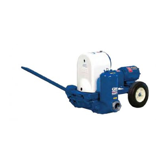
- Page 1 OM‐01510-OM03 June 29, 1981 Rev. E 12/05/18 Supersedes: OM-03569 INSTALLATION, OPERATION, AND MAINTENANCE MANUAL WITH PARTS LIST D SERIES PUMPS MODEL 4D-E3 3P GORMAN‐RUPP PUMPS www.grpumps.com 1981 Gorman‐Rupp Pumps Printed in U.S.A.
-
Page 2: Table Of Contents
TABLE OF CONTENTS INTRODUCTION ........... PAGE I - 1 WARNINGS SECTION A... - Page 3 TABLE OF CONTENTS (continued) PUMP AND SEAL DISASSEMBLY AND REASSEMBLY ......PAGE E - 10 Suction And Discharge Check Valve Removal .
-
Page 4: Introduction
Rupp pump. to those which could be dangerous to personnel: This is a D Series, positive displacement pump util izing a single‐action diaphragm to produce a straight‐through flow of liquid. The pump is ideally... - Page 5 D SERIES OM-01510 SAFETY ‐ SECTION A This information applies to D Series electric motor driven diaphragm pumps. Refer to the manual accompa nying the motor before attempting to Do not operate the pump without the ec centric and coupling guards in place begin operation.
- Page 6 OM-01510 D SERIES phase of the pump and motor before cordance with the National Electric connecting the power source. Do not Code. If there is a conflict between the run the pump if the voltage is not within instructions provided and N.E.C. speci...
-
Page 7: Installation - Section B
D SERIES OM-01510 INSTALLATION - SECTION B Review all SAFETY information in Section A. For further assistance, contact your Gorman‐Rupp distributor or the Gorman‐Rupp Company. Since pump installations are seldom identical, this Pump Dimensions section offers only general recommendations and practices required to inspect, position, and ar... -
Page 8: Positioning Pump
OM-01510 D SERIES or replaced to ensure maximum pump serv After the pump has been positioned, block the ice. wheels and secure the pump to prevent creeping. SUCTION AND DISCHARGE PIPING If the maximum shelf life has been exceeded, or if anything appears to be abnormal, contact your Pump performance is adversely effected by in... -
Page 9: Gauges
D SERIES OM-01510 tion be installed at or near the suction and dis suppressors must be installed in both suction and charge ports to absorb shock which would other discharge lines. If commercial surge suppressors wise be transmitted through the drive train and are not readily available, air chambers may be fab... -
Page 10: Fittings
OM-01510 D SERIES Fittings line smaller than the suction; a restricted discharge line will cause excessive friction Suction lines should be the same size as the pump loss resulting in overloading and destruc inlet. If reducers are used in suction lines, they tion of pump and drive components. -
Page 11: Electrical Connections
D SERIES OM-01510 The pump and motor were aligned and secured at ELECTRICAL CONNECTIONS the factory, but fastening hardware may have loos ened during shipment. It is imperative that this Before connecting the motor to the incoming pow hardware and the alignment be checked after the er, check that the electrical service available pump is installed and before operation. -
Page 12: Operation - Section C
OM-01510 D SERIES OPERATION - SECTION C Review all SAFETY information in Section A. ened diaphragm life. No positive shut‐off valve should be installed in the discharge Follow the instructions on all tags, labels and line. decals attached to the pump. -
Page 13: Accumulator Chamber Check
OM-01510 D SERIES flow begins to drop. If a vacuum suction gauge has ponents. avoid cleaning with cleaning sol been installed, monitor and record the readings vent. regularly to detect strainer blockage. In below freezing conditions, drain the water from the pump and the lines when the pump is not in op... -
Page 14: Troubleshooting - Section D
D SERIES OM-01510 TROUBLESHOOTING - SECTION D Review all SAFETY information in Section A. Before attempting to open or service the pump: 1. Familiarize yourself with this manual. 2. Shut off incoming power to the motor and lock it out to ensure that the pump will remain inoperative. - Page 15 OM-01510 D SERIES TROUBLE POSSIBLE CAUSE PROBABLE REMEDY PUMP REQUIRES Liquid solution too thick. Dilute if possible. TOO MUCH POWER Integral discharge check valve clogged Clean valve. or binding. Bearings in motor or gearbox Check bearings. worn or binding. PUMP CLOGS...
-
Page 16: Pump Maintenance And Repair Section E
D SERIES OM-01510 PUMP MAINTENANCE AND REPAIR ‐ SECTION E MAINTENANCE AND REPAIR OF THE WEARING PARTS OF THE PUMP WILL MAINTAIN PEAK OPERATING PERFORMANCE. IN GALLONS PER MINUTE AT 52 STROKES PER MINUTE STATIC STATIC DISCHARGE HEAD IN FEET... - Page 17 OM-01510 D SERIES SECTION DRAWING Figure 1. 4D-E3 3P PAGE E - 2 MAINTENANCE & REPAIR...
-
Page 18: Parts List
D SERIES OM-01510 PARTS LIST Pump Model 4D-E3 3P (From S/N 504867 up) If your pump serial number is followed by an “N”, your pump is NOT a standard production model. Contact the Gorman‐Rupp Company to verify part numbers. ITEM... - Page 19 OM-01510 D SERIES ILLUSTRATION Figure 2. Diaphragm Pot Assembly PAGE E - 4 MAINTENANCE & REPAIR...
-
Page 20: Diaphragm Pot Assembly
D SERIES OM-01510 PARTS LIST Diaphragm Pot Assembly ITEM PART PART NAME NUMBER POT-DIAPHRAM 6622 13010 ACCUMULATOR & SUCTION FLANGE 6625 13010 DISCHARGE FLANGE 6627 13040 PIPE PLUG P06 15079 DISCHARGE ELBOW 6626 13040 VALVE SEAT 6635 10010 FLAP VALVE ASSY... -
Page 21: Plunger Rod Assembly
OM-01510 D SERIES SECTION DRAWING 2 3 4 8.00 REF 10.78 HOLD Figure 3. 6959 Plunger Rod Assembly PAGE E - 6 MAINTENANCE & REPAIR... - Page 22 D SERIES OM-01510 PARTS LIST 6959 Plunger Rod Assembly ITEM PART PART NAME NUMBER BEARING CAP 6560 10010 -HEX HD CAPSCREW B0813S 15991 -HEX NUT D08S 15991 -LOCKWASHER J08 15991 PLUNGER ROD ASSEMBLY 6633 15990 DIAPHRAGM S1017 LUBRICATION FITTING S194...
- Page 23 OM-01510 D SERIES SECTION DRAWING Figure 4. Gearbox Assembly PAGE E - 8 MAINTENANCE & REPAIR...
-
Page 24: Gearbox Assembly
D SERIES OM-01510 PARTS LIST Gearbox Assembly ITEM PART NAME PART ITEM PART NAME PART NUMBER NUMBER GEAR HOUSING 6624 13040 DRIVE GEAR 6558 16040 CRANKSHAFT BEARING S374 SNAP RING S1004 PINION GEAR S1014 CRANKSHAFT GEAR 6641 15060 PINION SHAFT... - Page 25 OM-01510 D SERIES PUMP AND SEAL DISASSEMBLY AND REASSEMBLY Before attempting to open or service the Review all SAFETY information in Section A. pump: Follow the instructions on all tags, label and de 1. Familiarize yourself with this man cals attached to the pump.
- Page 26 D SERIES OM-01510 the valve seat (6) and check valve assembly to the Use a socket wrench to hold the plunger rod (5) se diaphragm pot. Pull the check valve assembly from curely, and unscrew the bearing cap assembly (1).
- Page 27 OM-01510 D SERIES gear cover (7). Pull the complete drive shaft sub‐ Install two 5/8‐11 UNC capscrews in the tapped assembly from the gear cover. holes in the crankshaft gear (3), and use a gear puller to slide the gear off the crankshaft. Retain the crankshaft gear key (8).
- Page 28 D SERIES OM-01510 NOTE If a hot oil bath is used to heat the bearings, both the oil and the container must be absolutely clean. If the oil has been previously used, it must be thor Bearings must be kept free of all dirt and oughly filtered.
- Page 29 OM-01510 D SERIES Press the drive shaft and assembled bearings into NOTE the eccentric housing (20), and secure with the re The pinion gear is a tight interference fit on the pin taining ring (24). ion shaft. To ease installation, the gear may be heated (and the shaft cooled) to a temperature dif...
- Page 30 D SERIES OM-01510 Plunger Rod Reassembly And Installation Diaphragm Installation (Figure 3) (Figure 3) Position the diaphragm (6) on the upper dia phragm plate (9), making sure the lip is properly Slide the plunger rod (5) through the upper dia...
- Page 31 OM-01510 D SERIES Refer to OPERATION, Section C before starting of the proper grade (see the following reference) the pump. through the vented plug hole until it flows out the oil level hole. Clean and reinstall the vented plug and the oil level plug.
- Page 32 For Warranty Information, Please Visit www.grpumps.com/warranty or call: U.S.: 419-755-1280 Canada: 519-631-2870 International: +1-419-755-1352 GORMAN‐RUPP PUMPS...
Need help?
Do you have a question about the D Series and is the answer not in the manual?
Questions and answers