GORMAN-RUPP PUMPS D Series Installation, Operation, And Maintenance Manual With Parts List
Hide thumbs
Also See for D Series:
Table of Contents
Advertisement
Quick Links
OTS
OM−02699−OE01
June 3, 1987
Rev. E 11-18-08
INSTALLATION, OPERATION,
AND MAINTENANCE MANUAL
WITH PARTS LIST
D SERIES PUMP
MODEL
3D−13
THE GORMAN-RUPP COMPANY D MANSFIELD, OHIO
www.grpumps.com
D
GORMAN-RUPP OF CANADA LIMITED
ST. THOMAS, ONTARIO, CANADA
Printed in U.S.A.
e
Copyright by the Gorman-Rupp Company
Advertisement
Table of Contents

Related Manuals for GORMAN-RUPP PUMPS D Series


Summary of Contents for GORMAN-RUPP PUMPS D Series
- Page 1 OM−02699−OE01 June 3, 1987 Rev. E 11-18-08 INSTALLATION, OPERATION, AND MAINTENANCE MANUAL WITH PARTS LIST D SERIES PUMP MODEL 3D−13 THE GORMAN-RUPP COMPANY D MANSFIELD, OHIO www.grpumps.com GORMAN-RUPP OF CANADA LIMITED ST. THOMAS, ONTARIO, CANADA Printed in U.S.A. Copyright by the Gorman-Rupp Company...
- Page 2 Register your new Gorman-Rupp pump online at www.grpumps.com/register. Valid serial number and e-mail address required. The engine exhaust from this product contains chemicals known to the State of California to cause cancer, birth defects or other reproductive harm. RECORD YOUR PUMP MODEL AND SERIAL NUMBER Please record your pump model and serial number in the spaces provided below.
-
Page 3: Table Of Contents
TABLE OF CONTENTS INTRODUCTION ........... PAGE I −... - Page 4 TABLE OF CONTENTS (continued) Suction And Discharge Check Valve Removal ....... PAGE E −...
-
Page 5: Introduction
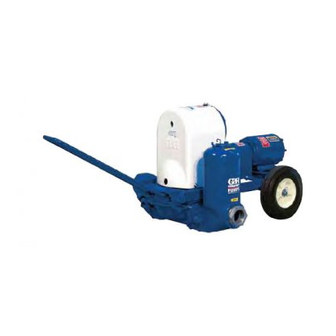
Rupp pump. from failure to follow the procedure. This is a D Series positive displacement pump, util- izing a single-action diaphragm to produce a straight-through flow of liquid. The pump is close- coupled to a 3.5 HP Briggs and Stratton gasoline engine. -
Page 6: Safety - Section A
D SERIES OM−02699−01 SAFETY - SECTION A This information applies to D Series en- gine driven diaphragm pumps. Refer to the manual accompanying the engine before attempting to begin operation. Do not operate the pump without the ec- centric and coupling guards in place over the rotating parts. - Page 7 OM−02699−01 D SERIES Fuel used by internal combustion en- Never install a positive shut-off valve in the gines presents an extreme explosion discharge line; discharge restrictions will and fire hazard. Make certain that all cause excessive friction loss resulting in...
-
Page 8: Installation − Section Bpage B
D SERIES OM−02699−01 INSTALLATION − SECTION B Review all SAFETY information in Section A. For further assistance, contact your Gorman-Rupp distributor or the Gorman-Rupp Company. Since pump installations are seldom identical, this Pump Dimensions section offers only general recommendations and... -
Page 9: Positioning Pump
OM−02699−01 D SERIES or replaced to ensure maximum pump serv- SUCTION AND DISCHARGE PIPING ice. Pump performance is adversely effected by in- If the maximum shelf life has been exceeded, or if creased suction lift, discharge elevation, and fric- anything appears to be abnormal, contact your tion losses. -
Page 10: Gauges
D SERIES OM−02699−01 tion be installed at or near the suction and dis- suppressors must be installed in both suction and charge ports to absorb shock which would other- discharge lines. If commercial surge suppressors wise be transmitted through the drive train and are not readily available, air chambers may be fab- greatly accelerate pump wear. -
Page 11: Fittings
OM−02699−01 D SERIES phragm chamber and result in short diaphragm DISCHARGE LINES life. Fittings Suction lines should be the same size as the pump The discharge line must be the same size inlet. If reducers are used in suction lines, they as, or larger than, the suction line. -
Page 12: Operation − Section C
OM−02699−01 D SERIES OPERATION − SECTION C Review all SAFETY information in Section A. OPERATION Follow the instructions on all tags, labels and decals attached to the pump. The pump is designed to operate at ap- proximately 60 cycles per minute through a gearbox with a 43.36:1 ratio at a maxi-... -
Page 13: Accumulator Chamber Check
OM−02699−01 D SERIES Accumulator Chamber Check In below freezing conditions, drain the water from the pump and the lines when the pump is not in op- Check periodically to ensure that there is sufficient eration. Also, clean out any solids by flushing with a air in the integral suction accumulator chamber. -
Page 14: Troubleshooting − Section D
D SERIES OM−02699−01 TROUBLESHOOTING − SECTION D Review all SAFETY information in Section A. Before attempting to open or service the pump: 1. Familiarize yourself with this man- ual. 2. Disconnect the engine spark plug wire ensure that the pump will re- main inoperative. - Page 15 OM−02699−01 D SERIES TROUBLE POSSIBLE CAUSE PROBABLE REMEDY PUMP REQUIRES Liquid solution too thick. Dilute if possible. TOO MUCH POWER Pump speed too high. Check engine output. Integral discharge check valve clogged Clean valve. or binding. Bearings in engine or gearbox Check bearings.
-
Page 16: Pump Maintenance And Repair - Section Epage E
D SERIES OM−02699−01 PUMP MAINTENANCE AND REPAIR - SECTION E MAINTENANCE AND REPAIR OF THE WEARING PARTS OF THE PUMP WILL MAINTAIN PEAK OPERATING PERFORMANCE. IN GALLONS PER MINUTE AT 60 STROKES PER MINUTE STATIC STATIC DISCHARGE HEAD IN FEET... - Page 17 OM−02699−01 D SERIES SECTION DRAWING PARTS PAGE Figure 1. Pump Model 3D-13 PAGE E − 2 MAINTENANCE & REPAIR...
-
Page 18: Parts Lists
D SERIES OM−02699−01 PARTS LIST Pump Model 3D-13 (From S/N 883285 Up) If your pump serial number is followed by an N", your pump is NOT a standard production model. Contact the Gorman-Rupp Company to verify part numbers. ITEM PART NAME PART MAT’L... -
Page 19: Diaphragm Pot Assembly
OM−02699−01 D SERIES SECTION DRAWING Figure 2. 46475−701 Diaphragm Pot Assembly PAGE E − 4 MAINTENANCE & REPAIR... - Page 20 D SERIES OM−02699−01 PARTS LIST 46475−701 Diaphragm Pot Assembly ITEM PART MAT’L PART NAME NUMBER CODE DISCHARGE FLANGE 5658 13040 STUD C0810 15991 HEX NUT 15991 FLAT WASHER KE08 15991 RD HD MACHINE SCREW X0404 15991 LOCKWASHER 15991 RD HD MACHINE SCREW...
- Page 21 OM−02699−01 D SERIES SECTION DRAWING Figure 3. Standard 5685 And Optional 5685B Plunger Rod Assembly PAGE E − 6 MAINTENANCE & REPAIR...
- Page 22 D SERIES OM−02699−01 PARTS LIST 5685 Standard Plunger Rod Assembly And 5685B Optional Plunger Rod Assembly ITEM PART MAT’L PART NAME NUMBER CODE ECCENTRIC CAP 5373 13010 ECCENTRIC BEARING 5610 14000 T-TYPE LOCKWASHER AK12 15991 JAM NUT AT12 15990 SPRING WASHER...
-
Page 23: Gearbox Assembly
OM−02699−01 D SERIES SECTION DRAWING Figure 4. 44161−007 Gearbox Assembly PAGE E − 8 MAINTENANCE & REPAIR... - Page 24 D SERIES OM−02699−01 PARTS LIST 44161−007 Gearbox Assembly ITEM PART MAT’L PART NAME NUMBER CODE GEAR HOUSING 5367 13010 SPACER SLEEVE S952 −−− HEX HD CAPSCREW B1004 15991 DRIVE SHAFT BEARING S702 −−− SPACER WASHER 5395 15990 DRIVE GEAR 5334...
-
Page 25: Pump And Seal Disassembly And Reassembly
OM−02699−01 D SERIES Suction And Discharge Check Valve Removal PUMP AND SEAL DISASSEMBLY AND REASSEMBLY (Figure 2) To service the suction and discharge check valves, Review all SAFETY information in Section A. remove the suction and discharge piping. To service the suction check valve assembly (26),... - Page 26 D SERIES OM−02699−01 (9) and the upper diaphragm plate (8). Inspect the phragm ring for wear or damage and replace as diaphragm and replace a required. necessary. It is not necessary to remove the draw- bar (21) from the diaphragm ring unless replace- If no further disassembly is required, see Dia- ment is required.
- Page 27 OM−02699−01 D SERIES and tag the shims or measure and record their Gearbox Reassembly And Installation thickness for ease of reassembly. (Figure 4) Slide the drive shaft and gear out of the gear hous- Inspect the shaft for distortion, nicks or scratches.
- Page 28 D SERIES OM−02699−01 thickness of shims (16) as previously removed. In- stall the washer (20) and eccentric cam key (18). Align the slot in the eccentric cam (15) with the key and press the eccentric cam onto the shaft until ful- Most cleaning solvents are toxic and ly seated against the washer (20).
- Page 29 OM−02699−01 D SERIES Lubricate the plunger rod assembly as described LUBRICATION in LUBRICATION, Section E. Secure the diaphragm pot assembly (28) to the di- Plunger Rod Assembly aphragm ring (18) with the hardware (26 and 27). (Figure 3) Suction And Discharge Check Valve Installa-...
- Page 30 D SERIES OM−02699−01 portant in areas where variable hot and cold temperatures are common. Engine Monitor the condition of the bearing lubri- (Figure 1) cant regularly for evidence of rust or mois- Refer to the engine manufacturer’s recommenda- ture condensation. This is especially im- tions or contact your local engine representative.
- Page 31 For U.S. and International Warranty Information, Please Visit www.grpumps.com/warranty or call: U.S.: 419−755−1280 International: +1−419−755−1352 For Canadian Warranty Information, Please Visit www.grcanada.com/warranty or call: 519−631−2870 THE GORMAN-RUPP COMPANY D MANSFIELD, OHIO GORMAN-RUPP OF CANADA LIMITED ST. THOMAS, ONTARIO, CANADA...
Need help?
Do you have a question about the D Series and is the answer not in the manual?
Questions and answers