Table of Contents
Advertisement
Quick Links
OVERVIEW
This detector model samples the air and the environmental temperature in the protected area. An alarm condition is raised whe n the detected
environmental smoke quantity, the temperature level or the thermal variation rate exceeds the alarm threshold.
COMPATIBILITY
This detector is compatible only with wireless systems based on the Sagittarius protocol.
For more specific information concerning compatibility refer to your fire security system supplier.
INSTALLATION - IMPORTANT NOTES
For detector spacing, placement and special applications refer to your specific national standards.
Mount the detector as far as possible from metal objects, metal doors, metal window openings, etc. as well as cable conductor s, cables
(especially from computers), otherwise the operating distance may greatly drop. The detector must NOT be installed near electronic devices
and computer equipment that can interfere with its wireless link quality.
This detector must be installed according precisely to the procedures described in this manual.
Test this detector after installation.
BEFORE INSTALLING THE DETECTOR
1) Extract the batteries cover from the back of the detector.
2) Power-up the detector removing the isolating tab in the battery
housing. LED indicators signal "Power up".
3) Link the detector to the Sagittarius wireless system (LINKING).
4) Check the WIRELESS LINK QUALITY.
6) Tag device's loop and address data (IDENTIFICATION).
7) Fix the detector supporting base to the wall (BASE INSTALLATION).
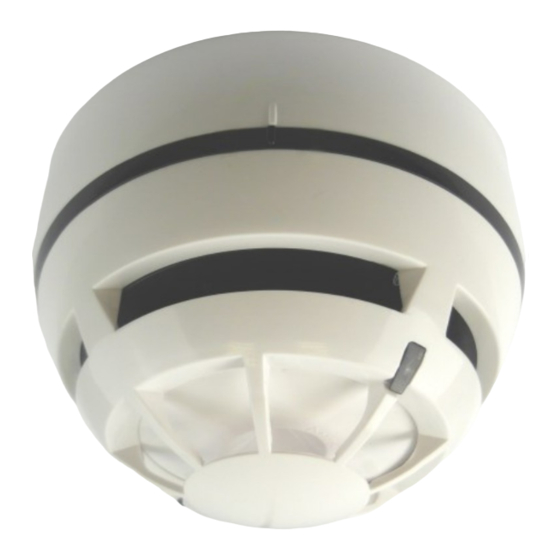
LED INDICATORS
Picture 1: provides visual indication for functional conditions and battery levels as indicated
in table 1.
Detector's status
Power up
Linking to the system
Link failure
Normal condition
Alarm
Battery 1 fault
Battery 2 fault
Both batteries fault
Other fault
Tamper
Lost link with wire to
wireless translator /
wireless expander
Type 1 Test Mode
Type 2 Test Mode
ARGUS SECURITY S.R.L. - Via del Canneto, 14 - 34015 - Muggia (TS) - Italy
L-MC-SG/865
BI-DIRECTIONAL WIRELESS ADDRESSABLE MULTICRITERIA
DETECTOR WITH VARIABLE SENSITIVITY
LEDs indication
1 second GREEN, then 4 X 0.5 second RED blink
Blinking GREEN until linking is completed
RED on (continuous)
LEDs off
Blinking RED: 0.5 second on and 0.5 second off
0.1 second ORANGE blink, then 5 seconds off
0.1 second GREEN blink, then 5 seconds off
0.1 second ORANGE, then 5 seconds off
0.1 second GREEN, then 5 seconds off
sequential ORANGE / GREEN 0.5 second blinking
LEDs off
LEDs off
Blinking GREEN every 1 second for 1 minute
GREEN on (continuous) for 30 minutes
LED INDICATORS
Table 1
Picture 1
www.argussecurity.it
Advertisement
Table of Contents

Related Manuals for Argus Security L-MC-SG/865


Summary of Contents for Argus Security L-MC-SG/865
- Page 1 Type 1 Test Mode Blinking GREEN every 1 second for 1 minute Type 2 Test Mode GREEN on (continuous) for 30 minutes Table 1 ARGUS SECURITY S.R.L. - Via del Canneto, 14 - 34015 - Muggia (TS) - Italy www.argussecurity.it...
- Page 2 LINKING Link switch The system is waiting to achieve a wireless child device (for further information refer to the translator’s or the Wirelex configuration software’s literature): 1) Move the link switch’s cursor from ON to the opposite side of its run (we will call it BLANK, since it carries no indication).
- Page 3 1) By following its specific instructions, apply the heat test device to the detector. 2) Wait a few seconds. 3) LED indicator will signal “Alarm”. Picture 7 ARGUS SECURITY S.R.L. - Via del Canneto, 14 - 34015 - Muggia (TS) - Italy www.argussecurity.it...
- Page 4 Table 5 NOTE OF THE DOCUMENT: Argus Security Srl hereby declares that this detector is in compliance with the essential requirements and other relevant provisions of Directive 1999/5/EC. A copy of the original Declaration of Conformity (Document: DoC LI01) is made available to the user on website: www.argussecurity.it ARGUS SECURITY S.R.L.
Need help?
Do you have a question about the L-MC-SG/865 and is the answer not in the manual?
Questions and answers