Table of Contents
Advertisement
Quick Links
Advertisement
Table of Contents

Related Manuals for Siemens SENTRON 3KF SITOR


Summary of Contents for Siemens SENTRON 3KF SITOR
- Page 1 3KF switch disconnectors with fuses...
- Page 3 Introduction General information Product description SENTRON Product line, product group Switch disconnectors 3KF switch disconnectors with Function and operation fuses Assembly and mounting Manual Connection and wiring Further accessories Maintenance Technical specifications Dimensional drawings and drilling templates Appendix ESD guidelines List of abbreviations Conversion tables 09/2019...
- Page 4 Note the following: WARNING Siemens products may only be used for the applications described in the catalog and in the relevant technical documentation. If products and components from other manufacturers are used, these must be recommended or approved by Siemens. Proper transport, storage, installation, assembly, commissioning, operation and maintenance are required to ensure that the products operate safely and without any problems.
-
Page 5: Table Of Contents
Table of contents Introduction ..............................7 General information ........................... 9 General information ........................9 Product description ..........................11 Function, performance features, application areas ..............11 Product line, product group ........................13 3KF switch disconnectors with fuses ..................13 4.1.1 Sizes ............................14 4.1.2 Installation type ........................ - Page 6 Table of contents 6.3.2 Sizes 2 to 4 ..........................40 6.3.2.1 Drilling template for sizes 2 to 5 LV HRC ................41 6.3.2.2 Drilling template for sizes 2 to 5 SITOR ................. 42 6.3.3 Size 5 ............................. 43 Standard rail mounting size 1 ....................44 6.4.1 Installation –...
- Page 7 Table of contents 8UD door-coupling rotary operating mechanism ..............83 8.4.1 Component overview ......................85 8.4.2 Types of delivery and versions ....................86 8.4.3 Mounting ..........................86 8.4.3.1 Mounting the handle on the door .................... 88 8.4.3.2 Calculating the length of the shaft/cutting the shaft ..............89 8.4.4 Functions and operation ......................
- Page 8 Table of contents 3KF switch disconnectors with fuses Manual, 09/2019, L1V30580914002A-01...
-
Page 9: Introduction
Introduction Purpose of this manual In this manual, the basic functions of switching devices of the "3KF switch disconnectors with fuses" series are described. The manual contains information on: ● Selection ● Configuration ● Commissioning Target group Planners, installation personnel, configuring engineers Required basic knowledge To understand this manual, you will need to have a general knowledge of low-voltage controls and power distribution. - Page 10 Introduction Symbol Meaning Symbol Meaning Phillips screwdriver PH Stranded conductor Slotted screwdriver Finely stranded conductor with end sleeves Trash bin Busbar Cut off in the trash bin Strip busbar Strip solid conductor Not OK Strip solid conductor with end sleeves Measure Strip solid conductor with end sleeves without insulating collar...
-
Page 11: General Information
General information General information Definitions of switch disconnectors with fuses 3KF SITOR is a variation of the proven 3KF LV HRC, provides optimized heat dissipation and permits the use of fuses with substantially higher power losses. In this way, fuses for semiconductor protection can be loaded with higher currents than conventional switch disconnectors with fuses. - Page 12 General information 2.1 General information NOTICE Qualified personnel Installation and maintenance must be carried out by qualified personnel. 3KF switch disconnectors with fuses Manual, 09/2019, L1V30580914002A-01...
-
Page 13: Product Description
Product description Function, performance features, application areas Function The 3KF switch disconnector is used to close, open, and protect rated currents from 32 A to 800 A. Performance features ● 3-pole and 4-pole versions for AC and DC applications ● 5 frame sizes from 32 A to 800 A (3KF SITOR to 850 A) ●... - Page 14 Product description 3.1 Function, performance features, application areas 3KF switch disconnectors with fuses Manual, 09/2019, L1V30580914002A-01...
-
Page 15: Product Line, Product Group
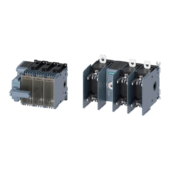
Product line, product group 3KF switch disconnectors with fuses ① 3KF SITOR ② 3KF LV HRC Size Rated current I 32 ... 80 125 ... 160 630 ... 800 Number of poles ✓ ✓ ✓ ✓ ✓ 4 (LC HRC only) ✓... -
Page 16: Sizes
Product line, product group 4.1 3KF switch disconnectors with fuses 4.1.1 Sizes 3KF switch disconnectors with fuses are available in the following sizes: ● Size 1: 32 – 63 – 80 A ● Size 2: 125 – 160 A ● Size 3: 250 A ●... - Page 17 Product line, product group 4.1 3KF switch disconnectors with fuses Size 3 ① 3KF SITOR with flat terminals ② 3KF LV HRC with flat terminals Size 4 ① 3KF SITOR with flat terminals ② 3KF LV HRC with flat terminals Size 5 ①...
-
Page 18: Installation Type
Product line, product group 4.1 3KF switch disconnectors with fuses 4.1.2 Installation type Installation type Size Floor mounting 1, 2, 3, 4, 5 Standard rail mounting 4.1.3 Connection Connection types Connections Size Flat terminals 2nd 3, 4, 5 Box terminals Flat terminals at rear 1, 2 Size 1 is available with box terminals for connecting stripped wires. - Page 19 Product line, product group 4.1 3KF switch disconnectors with fuses Sizes 2, 3, 4 and 5 are available with flat terminals for connection of cable lugs or busbars. ① Box terminals ② Flat terminals ③ Flat terminals at rear 3KF switch disconnectors with fuses Manual, 09/2019, L1V30580914002A-01...
-
Page 20: Operating Mechanism / Handle
Product line, product group 4.1 3KF switch disconnectors with fuses 4.1.4 Operating mechanism / handle All sizes of the 3KF LV HRC are available for manual operation from the front or side only. Note Figures The figures show the 3KD switch disconnector. The mounting principles are identical to the 3KF switch disconnector. - Page 21 Product line, product group 4.1 3KF switch disconnectors with fuses The 3KF LV HRC with manual operation can be equipped with a handle for direct operation on the switch disconnector or with door coupling handles for operation from outside the switchgear.
-
Page 22: Accessories
Product line, product group 4.2 Accessories Accessories 4.2.1 Additional poles All sizes of the 3KF can be equipped with additional poles, e.g. for the N or PE phase. A contact element, an N/PE terminal (with a permanent jumper) and an N terminal (with a removable jumper) are available. -
Page 23: Direct Operating Mechanism (3Kf Lv Hrc Only)
Product line, product group 4.2 Accessories 4.2.2 Direct operating mechanism (3KF LV HRC only) Direct operating mechanisms are used to operate the 3KF LV HRC directly on the switch disconnector. They are available for all sizes in gray and red/yellow (for Emergency Stop applications). -
Page 24: Auxiliary Switches
Product line, product group 4.2 Accessories Exploded view of all components for 8UD as below: ① Handle ② Coupling driver with tolerance compensation ③ Coupling driver without tolerance compensation ④ Extension shaft 4.2.4 Auxiliary switches Auxiliary switches are used to query the switch position (ON – OFF) of the 3KF. Auxiliary switches can be used with different switching instants (leading/simultaneous). - Page 25 Product line, product group 4.2 Accessories Circuit diagram for main contact, simultaneous and leading auxiliary switch: ① ② Auxiliary switch for size 1 Auxiliary switch for sizes 2 - 5 3KF switch disconnectors with fuses Manual, 09/2019, L1V30580914002A-01...
-
Page 26: Phase Barriers
Product line, product group 4.2 Accessories 4.2.5 Phase barriers On the 3KF, phase barriers are used between the flat terminals. The enlarge the isolating distance between the terminals. Phase barriers have to be used under certain circumstances (voltage level, switching category, mounting position of the switch). You will find more details on this in chapter Phase barriers (Page 52). -
Page 27: Cable Connection Covers (3Kf Lv Hrc Only)
Product line, product group 4.2 Accessories 4.2.6 Cable connection covers (3KF LV HRC only) Cable connection covers can be used for additional touch protection on a 3KF (LV HRC only) with flat terminals. Cable connection covers on a 3KF, size 5 as an example Note Cable connection covers can also be mounted on the operating mechanism module of the 3KF to ensure a consistent design or to cover the wiring of auxiliary switches. -
Page 28: Exploded Views
Product line, product group 4.3 Exploded views Exploded views 4.3.1 Size 1 – 3KF LV HRC ① ⑥ 3KF switch disconnector with fuses N/PE terminal ② ⑦ Direct operating mechanism Fourth pole ③ ⑧ 8UD door-coupling rotary operating mechanism Auxiliary switch module ④... -
Page 29: Size 1 - 3Kf Sitor
Product line, product group 4.3 Exploded views 4.3.2 Size 1 – 3KF SITOR ① ⑤ 3KF switch disconnector with SITOR fuses N/PE terminal with permanent jumper ② ⑥ 8UD door-coupling rotary operating mechanism Fourth pole ③ ⑦ Electronic fuse monitoring Auxiliary switch module ④... -
Page 30: Sizes 2 To 5 - 3Kf Lv Hrc
Product line, product group 4.3 Exploded views 4.3.3 Sizes 2 to 5 – 3KF LV HRC ① ⑦ 3KF switch disconnector with fuses Electronic fuse monitoring ② ⑧ Direct operating mechanism N/PE terminal (with permanent jumper) ③ ⑨ 8UD door-coupling rotary operating mechanism Neutral conductor terminal (with removable jumper) ④... -
Page 31: Sizes 2 To 5 - 3Kf Sitor
Product line, product group 4.3 Exploded views 4.3.4 Sizes 2 to 5 – 3KF SITOR ① ⑤ 3KF switch disconnector with SITOR fuses N/PE terminal (with permanent jumper) ② ⑥ 8UD door-coupling rotary operating mechanism Neutral conductor terminal (with removable jumper) ③... -
Page 32: Article Number Structure
Product line, product group 4.4 Article number structure Article number structure Article numbers for switch disconnectors with fuses 3KF switch disconnectors with fuses Manual, 09/2019, L1V30580914002A-01... -
Page 33: Function And Operation
Function and operation Note The manually operated 3KF can be operated with a handle for direct operation on the switch disconnector or outside the cabinet with the door-coupling rotary operating mechanism. You will find more details on this in chapters Direct operating mechanism (Page 82) and 8UD door-coupling rotary operating mechanism (Page 83). - Page 34 Function and operation 3KF with door-coupling rotary operating mechanism 3KF switch disconnectors with fuses Manual, 09/2019, L1V30580914002A-01...
-
Page 35: Assembly And Mounting
Assembly and mounting Assembly of parts in the scope of supply Rating plates With the rating plates contained in the scope of supply of the 3KF switch disconnector with fuses, the phases that are connected to the switching poles of the 3KF are marked. Note As an alternative to the rating plates supplied, other rating plates with the right size can be used. -
Page 36: Mounting Position
Assembly and mounting 6.2 Mounting position Mounting position Valid for all sizes. WARNING Fire hazard Some combinations of mounting position and load may cause flashovers between the terminals if no phase barriers or cable connection covers are used. Use phase barriers or cable connection covers if applicable according to chapter Phase barriers (Page 52). -
Page 37: Size 1 - Lv Hrc With Box Terminals
Assembly and mounting 6.3 Floor mounting 6.3.1.2 Size 1 – LV HRC with box terminals The scope of supply of the switch includes mounting brackets that are fastened to the rear of the switch. Note If the 3KF is mounted on a standard mounting rail, the mounting brackets are not required. 3KF switch disconnectors with fuses Manual, 09/2019, L1V30580914002A-01... -
Page 38: Sizes 1 And 2 With Flat Terminals At The Rear
Assembly and mounting 6.3 Floor mounting 6.3.1.3 Sizes 1 and 2 with flat terminals at the rear 6.3.1.4 Drilling template size 1 – SITOR Size Poles Terminal A [mm] B [mm] C [mm] D [mm] E [mm] F [mm] G [mm] H [mm] Box terminals 138.5... -
Page 39: Drilling Template Size 1 - Flat Terminals At The Rear
Assembly and mounting 6.3 Floor mounting 6.3.1.5 Drilling template size 1 – flat terminals at the rear [mm] 3KF1...-..R.. 36.5 143.9 114.6 70.5 130.5 66.5 36.5 177.5 3KF switch disconnectors with fuses Manual, 09/2019, L1V30580914002A-01... -
Page 40: Drilling Template Size 2 - Flat Terminals At The Rear
Assembly and mounting 6.3 Floor mounting 6.3.1.6 Drilling template size 2 – flat terminals at the rear [mm] 3KF2...-..R.. 190.7 110.5 80.5 157.2 210.6 3KF switch disconnectors with fuses Manual, 09/2019, L1V30580914002A-01... -
Page 41: Drilling Template Size 1 - Lv Hrc
Assembly and mounting 6.3 Floor mounting 6.3.1.7 Drilling template size 1 – LV HRC 3KF switch disconnectors with fuses Manual, 09/2019, L1V30580914002A-01... -
Page 42: Sizes 2 To 4
Assembly and mounting 6.3 Floor mounting 6.3.2 Sizes 2 to 4 Size 2.0 ... 2.5 Nm 3.0 mm 3 and 4 5.0 ... 6.0 Nm 5.0 mm The mounting brackets can be used in horizontal or vertical alignment dependent on the dimensions of the mounting location. -
Page 43: Drilling Template For Sizes 2 To 5 Lv Hrc
Assembly and mounting 6.3 Floor mounting 6.3.2.1 Drilling template for sizes 2 to 5 LV HRC Size 204.2 15.5 39.5 30.5 61.5 304.1 38.5 46.5 413.4 23.5 13.5 60.5 Dimensions in mm Note Scale The drilling template is not in scale 1:1. 3KF switch disconnectors with fuses Manual, 09/2019, L1V30580914002A-01... -
Page 44: Drilling Template For Sizes 2 To 5 Sitor
Assembly and mounting 6.3 Floor mounting 6.3.2.2 Drilling template for sizes 2 to 5 SITOR Size ∅ D 192.3 187.6 248.9 60.5 77.5 288.6 283.5 77.5 393.9 93.5 Dimensions in mm Size 11.5 17.25 129.8 178.5 22.5 190.5 13.5 50.5 152.5 Dimensions in mm 3KF switch disconnectors with fuses... -
Page 45: Size 5
Assembly and mounting 6.3 Floor mounting 6.3.3 Size 5 Drilling template for size 5 ① Dimensions of the switch enclosure (without phase barriers and terminals) Poles A [mm] B [mm] D [mm] Note Scale The drilling template is not in scale 1:1. 3KF switch disconnectors with fuses Manual, 09/2019, L1V30580914002A-01... -
Page 46: Standard Rail Mounting Size 1
Assembly and mounting 6.4 Standard rail mounting size 1 Standard rail mounting size 1 6.4.1 Installation – front operating mechanism and lateral operating mechanism on the right 6.4.2 Deinstallation – front operating mechanism and lateral operating mechanism on the right 3KF switch disconnectors with fuses Manual, 09/2019, L1V30580914002A-01... -
Page 47: Installation - Lateral Operating Mechanism On The Left
Assembly and mounting 6.4 Standard rail mounting size 1 6.4.3 Installation – lateral operating mechanism on the left 6.4.4 Deinstallation – lateral operating mechanism on the left 3KF switch disconnectors with fuses Manual, 09/2019, L1V30580914002A-01... - Page 48 Assembly and mounting 6.4 Standard rail mounting size 1 3KF switch disconnectors with fuses Manual, 09/2019, L1V30580914002A-01...
-
Page 49: Connection And Wiring
Connection and wiring Main circuit connection The connections of the main conductors for the various sizes are described below. ● Tools required ● Recommended tightening torque range ● Permissible conductor cross-sections 7.1.1 Approved circuit diagrams The following circuits are permissible AC applications AC applications, 3-pole AC applications, 4-pole... - Page 50 Connection and wiring 7.1 Main circuit connection DC applications, 2 poles connected in series – max. 220 V DC DC applications, 3 poles connected in series – max. 440 V DC DC applications, 3 poles connected in series – max. 440 V DC 3KF switch disconnectors with fuses Manual, 09/2019, L1V30580914002A-01...
-
Page 51: Box Terminals
Connection and wiring 7.1 Main circuit connection 7.1.2 Box terminals The box terminals of the 3KF are dimensioned for the simultaneous connection of a round cable and a busbar (solid copper or flexibar). Stripping insulation Size A [mm] 3KF switch disconnectors with fuses Manual, 09/2019, L1V30580914002A-01... - Page 52 Connection and wiring 7.1 Main circuit connection Technical specifications of box terminals Size Cable type Cable material Tool Conductor cross-section [mm / mm²] Copper 1 x 1 to 6 Copper 1 x 6…35 Copper 1 x 1 to 25 4 mm, 5.0 ...
-
Page 53: Flat Terminals
Connection and wiring 7.1 Main circuit connection 7.1.3 Flat terminals Sizes 2 to 4 Size 5 DIN ISO 46234 [mm DIN ISO 46235 [mm [mm x mm] 3KF2...-..F.. 1 × 2.5 ... 95 1 × 25 ... 70 1 × 15 x 3 2 x 2.5 ... -
Page 54: Connection Accessories
Connection and wiring 7.1 Main circuit connection 7.1.4 Connection accessories 7.1.4.1 Phase barriers Phase barriers are used on the 3KF with flat terminals as additional insulation between the terminals. 3KF SITOR UL UL 508 L ≧ 6.35 mm [0.25 in] Branch UL 508 L ≧... - Page 55 Connection and wiring 7.1 Main circuit connection DANGER Danger of arcing. Will cause death or serious injury. In UL applications, a phase barrier is mandatory. Installation of phase barriers 3KF switch disconnectors with fuses Manual, 09/2019, L1V30580914002A-01...
- Page 56 Connection and wiring 7.1 Main circuit connection Installation locations of phase barriers 3KF front operating mechanism, 3-pole, operating mechanism module on the left-hand side 3KF, front operating mechanism, 3- 3KF, front operating mechanism, 4-pole, operating mechanism pole, operating mechanism module in module in the center the center 3KF, lateral operating mechanism...
- Page 57 Connection and wiring 7.1 Main circuit connection Minimum clearance to end of non-isolated part of cable lug Phase barriers need a minimum clearance from the end of the phase barrier to the end of the non-isolated part of the installed cable lug. Size A [mm] 2 ...
-
Page 58: Cable Connection Covers (3Kf Lv Hrc Only)
Connection and wiring 7.1 Main circuit connection 7.1.4.2 Cable connection covers (3KF LV HRC only) Cable connection covers are used on a 3KF LV HRC with flat terminals if touch protection is required. Note Cable connection covers fulfill the same purpose as phase barriers. If additional touch protection of the terminals is necessary, cable connection covers can be used instead of phase barriers. -
Page 59: Auxiliary Circuit Connection
Connection and wiring 7.2 Auxiliary circuit connection Auxiliary circuit connection 7.2.1 Auxiliary switches You will find more information on mounting auxiliary switches in chapter Mounting auxiliary switches (Page 66). 7.2.2 Auxiliary switches for size 1 Auxiliary switches for size 1 are available in two versions: With cable These are delivered with soldered 50 cm long cables. -
Page 60: Auxiliary Switch For Sizes 2 To 5
Connection and wiring 7.3 Contact numbers 7.2.3 Auxiliary switch for sizes 2 to 5 Sizes 2 to 5 of the 3KF use 3SU1 contact modules of the SIRIUS ACT series as auxiliary switches. Contact numbers This chapter describes contact numbers for wiring plans. 3KF switch disconnectors with fuses Manual, 09/2019, L1V30580914002A-01... -
Page 61: Main Circuit
Connection and wiring 7.3 Contact numbers 7.3.1 Main circuit For identification of the main terminals in wiring diagrams, the relevant rating plates are included in the scope of supply of each 3KF switch disconnector and of all additional poles. As an alternative to the rating plates supplied, other rating plates suitable for use in an industrial environment can also be used (e.g. - Page 62 Connection and wiring 7.3 Contact numbers Size 2 Sizes 3 to 5 Note If a one-pole auxiliary switch is mounted, only the numbers in the first line are used. If a two- pole auxiliary switch is mounted, the upper line of numbers on the operating module is used for the upper contact and the lower line for the lower contact of the auxiliary switch module.
- Page 63 Connection and wiring 7.3 Contact numbers ① Sizes 1, 2, auxiliary switch module, standard version ② Sizes 1, 2, auxiliary switch module, versions with test function or leading switching instant Figure 7-1 Auxiliary switch modules Note For the first digit, two sets of digits are printed on the standard version of the auxiliary switch module, because two of these modules can be used on one 3KF switch disconnector.
- Page 64 Connection and wiring 7.3 Contact numbers ① ② Sizes 2, 3, 4, 5, 1-pole auxiliary switch Sizes 2, 3, 4, 5, 2-pole auxiliary switch 3KF switch disconnectors with fuses Manual, 09/2019, L1V30580914002A-01...
-
Page 65: Further Accessories
Further accessories Auxiliary switches Purpose of the auxiliary switches Auxiliary switches are used to query the switch position of the main contacts of the 3KF. They can be retrofitted if required. Switching instant of the auxiliary switches You can set the auxiliary switch to different switching instants (leading/simultaneous). You will find more information on this in chapter Mounting auxiliary switches (Page 66). - Page 66 Further accessories 8.1 Auxiliary switches Switching to the test position 3KF with direct operating mechanism Test function on door-coupling rotary operating mecha- nism, 8UD series Note The test function is only possible on the 3KF with front operating mechanism. For size 1, the test function is only possible on switch disconnector versions in which the operating mechanism module is not mounted in the center.
- Page 67 Further accessories 8.1 Auxiliary switches Availability of the test function and switching instants for auxiliary switches Size Operation Type of handle Test function Switching instant Simultaneously Leading Front operating Direct mechanism, oper- ating mechanism module on left Front operating Direct mechanism, oper- ating mechanism module in center...
-
Page 68: Mounting Auxiliary Switches
Further accessories 8.1 Auxiliary switches 8.1.1 Mounting auxiliary switches 8.1.1.1 Size 1 For size 1, microswitches with changeover contacts (NO/NC contacts) are used that can be snapped into an auxiliary switch module. Up to two auxiliary switches can be mounted in every auxiliary switch module. Auxiliary switch modules are mounted like an additional pole on the side of the 3KF switch disconnector (for more information on mounting auxiliary switch modules, see chapter Mounting additional poles (Page 76). -
Page 69: Sizes 2 To 5
Further accessories 8.1 Auxiliary switches Note The 3KD9103-6 and 3KD9103-7 auxiliary switch modules can only be mounted directly next to the operating mechanism module of the 3KF switch disconnector. You will find more information on this in chapter Mounting additional poles (Page 76). 8.1.1.2 Sizes 2 to 5 For sizes 2, 4, and 5 of the 3KF, contact elements of the 3SU1 series are snapped into the... - Page 70 Further accessories 8.1 Auxiliary switches Installation location Up to three auxiliary switches can be mounted on a size 2 3KF, and up to four auxiliary switches on sizes 3, 4, and 5. Test function If the 3KF is switched to the test position, the auxiliary switches in all installation locations ①...
-
Page 71: Availability Of The Test Function
Further accessories 8.2 Additional poles 8.1.2 Availability of the test function The test function is possible for certain combinations of 3KF switch disconnector and handle: Version of the 3KF Mounted handle Test function Front operating Direct operating mechanism mechanism 8UD door-coupling rotary operating mech- anism Lateral operating 8UD door-coupling rotary operating mech-... - Page 72 Further accessories 8.2 Additional poles 4th contact element An additional pole with a switching function is identical to the poles mounted on the 3KF. It can be installed to upgrade a 3-pole 3KF switch disconnector to a 4-pole switch disconnector if the N conductor is to be connected.
-
Page 73: Possible Mounting Positions For Additional Poles And Auxiliary Switch Modules
Further accessories 8.2 Additional poles 8.2.2 Possible mounting positions for additional poles and auxiliary switch modules 8.2.2.1 Size 1 Size 1 – LV HRC 3KF switch disconnectors with fuses Manual, 09/2019, L1V30580914002A-01... - Page 74 Further accessories 8.2 Additional poles ① Neutral conductor terminal 3KF9106-2AA00 ② N/PE terminal 3KF9106-8AA00 ③ Fourth pole 3KF9105-2AA00 ④ Auxiliary switches 3KD9103-1 3KD9103-2 3KD9103-3 3KD9103-4 ⑤ Auxiliary switch module 3KD9103-5 3KD9103-6 3KD9103-7 Lateral auxiliary switch module 3KD..-4..Note Size 1 of the 3KF with lateral operating mechanism has a wider side cover next to the operating mechanism module with a mounting location for an auxiliary switch.
- Page 75 Further accessories 8.2 Additional poles Size 1 – SITOR ① Neutral conductor terminal 3KF9106-2AA00 ② N/PE terminal 3KF9106-8AA00 ③ Fourth pole 3KF9105-2BA00 ④ Auxiliary switches 3KD9103-1 3KD9103-2 3KD9103-3 3KD9103-4 ⑤ Auxiliary switch module 3KD9103-5 3KD9103-6 3KD9103-7 Note Note • 3KF switch disconnectors for AC applications can accommodate a maximum of 4 contact elements;...
-
Page 76: Sizes 3, 4 And 5
Further accessories 8.2 Additional poles Long screw Short screw 8.2.2.2 Sizes 3, 4 and 5 Sizes 3, 4 and 5 – 3KF LV HRC ① Fourth pole ② Neutral conductor terminal ③ N/PE terminal 3KF switch disconnectors with fuses Manual, 09/2019, L1V30580914002A-01... - Page 77 Further accessories 8.2 Additional poles Sizes 3, 4 and 5 – 3KF SITOR ① Fourth pole ② Neutral conductor terminal ③ N/PE terminal NOTICE Material damage Risk of malfunction or damage to the device. 3KF switch disconnectors for AC applications can accommodate a maximum of 4 contact elements;...
-
Page 78: Mounting Additional Poles
Further accessories 8.2 Additional poles 8.2.3 Mounting additional poles Remove the side cover on the side of the 3KF on which the additional pole is to be mounted. Size 1 Sizes 2, 3, 4 and 5 Size 3, 4, 5 Turn the shaft of the additional pole for mounting on the 3KF into the correct position. - Page 79 Further accessories 8.2 Additional poles 4th contact element Size 1: On auxiliary switch modules and N and N/PE poles of size 1, two lines must be aligned on the enclosure and the shaft. The 4th pole has to be turned clockwise as far as it will go. Sizes 2 to 5: The 4th pole has to be turned clockwise as far as it will go.
- Page 80 Further accessories 8.2 Additional poles Reassemble the side cover with the longer screws that are included in the scope of supply of the additional pole. Size 1 Sizes 2 to 5 3KF switch disconnectors with fuses Manual, 09/2019, L1V30580914002A-01...
- Page 81 Further accessories 8.2 Additional poles Mounting of the auxiliary switch module on the 3KF with flat terminals at the rear Mounting of two modules on one side of the switch On size 1 of the 3KF, two modules can be used on one side of the switch disconnector (see chapter Size 1 (Page 71)).
-
Page 82: Removing The Jumper At N Terminal
Further accessories 8.2 Additional poles The short version of screw is used if the additional pole is used, the longer version is used if an additional pole is used in combination with an auxiliary switch module. The scope of supply of the additional poles also includes rating plates that can be used to label the phase type (N, PE). -
Page 83: Reattaching The Jumper
Further accessories 8.2 Additional poles 8.2.4.2 Reattaching the jumper Size of the 3KF With box terminals 3 mm 1.3 ... 1.7 Nm With flat terminals 3 mm 1.3 ... 1.7 Nm With box terminals 4 mm 1.9 ... 2.5 Nm With flat terminals 5 mm 4.3 ... -
Page 84: Direct Operating Mechanism
Further accessories 8.3 Direct operating mechanism Direct operating mechanism 8.3.1 Versions Direct operating mechanism, standard ver- Direct operating mechanism, standard version, sion, gray red/yellow Note Handles in the colors red/yellow are used for Emergency Off applications and the handles in gray are used for all other applications. -
Page 85: Interlocking
Further accessories 8.4 8UD door-coupling rotary operating mechanism 8.3.2 Interlocking The 3KF switch disconnectors can be connected in the OFF position. Size Ø [mm] 1, 2, 3 4 ... 6 4, 5 4 ... 8 8UD door-coupling rotary operating mechanism The door-coupling rotary operating mechanism can be used to operate the switch disconnector from outside the cabinet door. - Page 86 Further accessories 8.4 8UD door-coupling rotary operating mechanism 8UD series Modern design of the handles identical with the handles which are used on the new range of 3VA MCCBs. ● Locking function on the handle with padlocks ● Optional illumination of switching symbols on the handle ●...
-
Page 87: Component Overview
Further accessories 8.4 8UD door-coupling rotary operating mechanism 8.4.1 Component overview ① Handle (including front cover, seal and screws for mounting on front door) ② Inscription label ③ Coupling driver with tolerance compensation ④ Coupling driver without tolerance compensation ⑤ Extension shaft ⑥... -
Page 88: Types Of Delivery And Versions
Further accessories 8.4 8UD door-coupling rotary operating mechanism 8.4.2 Types of delivery and versions The 8UD is available as a complete unit ready for installation. This includes a handle without illumination, a coupling driver with tolerance compensation and a 300 mm long extension shaft. All components are also available separately. - Page 89 Further accessories 8.4 8UD door-coupling rotary operating mechanism Note 8UD with illumination The lock hasp diameter of 3 mm is only required when the illuminated version of the 8UD is used. Note Shaft positioning You will find the assignment of the center hole in the cabinet door (shaft) to the position of the 3KF switch disconnector in the cabinet in the dimensional drawings of the 3KF.
-
Page 90: Mounting The Handle On The Door
Further accessories 8.4 8UD door-coupling rotary operating mechanism 8.4.3.1 Mounting the handle on the door The following modifications of the handle can only be performed as long as the handle has not been mounted on the cabinet door: ● Deactivation of the door interlocking ●... -
Page 91: Calculating The Length Of The Shaft/Cutting The Shaft
Further accessories 8.4 8UD door-coupling rotary operating mechanism 8.4.3.2 Calculating the length of the shaft/cutting the shaft 3KF with front operating mechanism A min A max 3KF2 293.0 386.5 93.5 3KF3 355.5 422.0 129.8 3KF4 320.0 391.0 110.0 3KF5 307.0 405.5 152.5 Length of the shaft... - Page 92 Further accessories 8.4 8UD door-coupling rotary operating mechanism 3KF with lateral operating mechanism A min 3KF3 61.0 22.5 Length of the shaft Size of the 3KF A [mm] Tolerance B [mm] 1, 2 X + 14 X - 1 X + 20 X - 1 X + 34 X - 1...
- Page 93 Further accessories 8.4 8UD door-coupling rotary operating mechanism ① Mark dimension B on the shaft ② Saw the shaft to length A ③ Deburr the cutting edges of the shaft to enable proper mounting The dimensions for A and B can be found in the section "Cutting the shaft" in this chapter. Attach the coupling driver to the shaft Push the shaft into the driver as far as it will go.
- Page 94 Further accessories 8.4 8UD door-coupling rotary operating mechanism Push the shaft into the 3KF as far as marking B. Sizes 1 to 5 Size 1.5 mm 0.8 ... 1.0 Nm 2.0 mm 1.5 ... 2.0 Nm 2.5 mm 4.0 ... 4.5 Nm 3.0 mm 7.0 ...
- Page 95 Further accessories 8.4 8UD door-coupling rotary operating mechanism Close the cabinet door carefully the first time to check correct alignment between the 8UD handle and the 3KF switch. NOTICE Material damage Risk of damage to the device. When the cabinet door is opened, the 8UD coupling head is deflected slightly downwards. This deflection is caused by tolerances between the 8UD shaft and the mounting point on the 3KF, as well as by tolerances between the 3KF and the mounting plate or standard mounting rail in the cabinet.
-
Page 96: Functions And Operation
Further accessories 8.4 8UD door-coupling rotary operating mechanism Closing the cabinet door ① Coupling head deflected slightly downwards – cabinet door can be closed. ② Coupling head deflected strongly downwards – cabinet door cannot be closed. ③ Coupling head deflected strongly downwards – 8UD handle with shaft jack (8UD1900-0FA00) – cabinet door can be closed 8.4.4 Functions and operation... -
Page 97: Overriding Door Interlocking
Further accessories 8.4 8UD door-coupling rotary operating mechanism NOTICE Material damage Risk of damage to the device. If a force of at least 800 N pulls at the door when door interlocking is activated, the operating mechanism can be irreparably damaged. 8.4.4.2 Overriding door interlocking Door interlocking can be overridden by a deliberate action. -
Page 98: Deactivating Door Interlocking
Further accessories 8.4 8UD door-coupling rotary operating mechanism 8.4.4.3 Deactivating door interlocking Door interlocking can also be permanently deactivated. To deactivate door interlocking, the lever on the rear of the front cover of the 8UD must be turned to the vertical position using a slotted screwdriver (2.5 mm). ①... - Page 99 Further accessories 8.4 8UD door-coupling rotary operating mechanism NOTICE Material damage Risk of damage to the device. When deactivating door interlocking, ensure that the 8UD handle and the 3KF switch disconnector are in the same position (both ON or OFF) before you close the cabinet door. Otherwise the operating mechanism can be damaged.
-
Page 100: Interlocking
Further accessories 8.4 8UD door-coupling rotary operating mechanism Note The coupling drivers are also available without tolerance compensation (accessory). They are used for the 3KF with lateral operating mechanism. 8.4.4.4 Interlocking 8UD handles in as-delivered condition can be locked with padlocks in the OFF position. If the handle was locked in the OFF position, the 3KF switch disconnector cannot be closed and the cabinet door cannot be opened. - Page 101 Further accessories 8.4 8UD door-coupling rotary operating mechanism Size 1, 2 1.0 ... 1.2 Nm 3, 4, 5 2.0 ... 2.5 Nm Mount the operating lever on the front cover again. Test interlocking in the ON position before installation in the cabinet door. The rotary operating mechanisms can be locked with up to three padlocks with a shackle diameter of 4.5 to 9.5 mm.
-
Page 102: Test Function For Auxiliary Switches
Further accessories 8.4 8UD door-coupling rotary operating mechanism 8.4.4.6 Test function for auxiliary switches The 3KF provides a test function for mounted auxiliary switches that is supported by the 8UD door-coupling rotary operating mechanism. Note You will find more details on the test function in chapter Auxiliary switches (Page 63). Switching to the test position The test position is located 20°... -
Page 103: Assign A Switch Position Between The 8Ud Handle And The 3Kf
Further accessories 8.4 8UD door-coupling rotary operating mechanism 8.4.4.7 Assign a switch position between the 8UD handle and the 3KF The coupling drivers, shafts and the operating mechanism module of the 3KF are equipped with a tongue and groove connection to maintain the usual position for the 8UD handle ("OFF"... - Page 104 Further accessories 8.4 8UD door-coupling rotary operating mechanism Modification of tongue-and-groove joint on coupling driver Remove the tongue and groove connection using a tool, e.g. a screwdriver, by pressing against it from inside. Mount it in the required position again outside. 3KF switch disconnectors with fuses Manual, 09/2019, L1V30580914002A-01...
-
Page 105: Accessories For 8Ud
Further accessories 8.4 8UD door-coupling rotary operating mechanism 8.4.5 Accessories for 8UD 8.4.5.1 Shaft coupling The shaft coupling is used if the shaft length of 300 / 600 mm is not sufficient and needs to be extended. For sizes 1 to 4 of the 3KF Size A [mm] 1, 2... -
Page 106: Shaft Jack For Sizes 1 And 2
Further accessories 8.4 8UD door-coupling rotary operating mechanism 8.4.5.2 Shaft jack for sizes 1 and 2 The shaft jack can be used if the coupling head is too widely deflected and the cabinet door cannot be closed due to a mechanical collision between the coupling head and the 8UD handle. -
Page 107: Inscription Label
Further accessories 8.4 8UD door-coupling rotary operating mechanism 8.4.5.3 Inscription label The labeling plate can be used for inscription directly on the front of the 8UD handle. The inscription area is 44.5 x 14.5 mm. Mounting Remove the knockout on the rear panel of the front cover of the 8UD. Snap the labeling plate onto the front cover of the 8UD. - Page 108 Further accessories 8.4 8UD door-coupling rotary operating mechanism 3KF switch disconnectors with fuses Manual, 09/2019, L1V30580914002A-01...
-
Page 109: Maintenance
Maintenance No maintenance procedures are necessary. 3KF switch disconnectors with fuses Manual, 09/2019, L1V30580914002A-01... - Page 110 Maintenance 3KF switch disconnectors with fuses Manual, 09/2019, L1V30580914002A-01...
-
Page 111: Technical Specifications
Technical specifications Regulations IEC 60947-1, IEC 60947-3, VCE 0660 Part 107 Size General technical details Rated uninterrupted current I Conventional free-air thermal current th 1) For fuse links acc. to IEC 60269-2 00 and 000 1 and 2 and 3 and 2 Rated operational voltage U At 50 Hz / 60 Hz AC (tolerance up to •... - Page 112 Technical specifications Regulations IEC 60947-1, IEC 60947-3, VCE 0660 Part 107 Size Let-through current combined with fuse 10.4 18.2 28.7 39.4 58.5 At 400 / 500 V AC • 11.2 16.87 30.31 41.14 49.95 At 690 V AC • Let-through value combined with fuse kA²s 33.2...
-
Page 113: Technical Specifications - Accessories
Technical specifications 10.1 Technical specifications – accessories Regulations IEC 60947-1, IEC 60947-3, VCE 0660 Part 107 Size Main conductor connection Conductor cross-section, max. mm² 2x150 2x300 Busbar systems, max. dimensions 1x9x2 1x20x3 1x25x 1x30x 1x50x10 (number x width x thickness) Tightening torque 5 ... - Page 114 Technical specifications 10.1 Technical specifications – accessories Sizes 2 to 5 Standards IEC 60947-5-1, IEC 60947-5-5 General technical details Conventional free-air thermal current I Rated insulation voltage U Degree of pollution acc. to IEC 60947-1 Class 3 Rated impulse withstand voltage U Switching frequency 3600 Contact reliability...
- Page 115 Technical specifications 10.1 Technical specifications – accessories Operating behavior Rated operational current I At AC-12 At AC-15 Up to 230 V At 400 V At DC-12 At 24 V At 48 V At 110 V At 230 V At DC-13 At 24 V At 48 V At 110 V...
- Page 116 Technical specifications 10.1 Technical specifications – accessories 3KF switch disconnectors with fuses Manual, 09/2019, L1V30580914002A-01...
-
Page 117: Dimensional Drawings And Drilling Templates
Dimensional drawings and drilling templates 11.1 Distance from grounded parts and between two 3KFs 3KF LV HRC Size Terminal A [mm] B [mm] C [mm] D [mm] Box terminals Flat terminals Flat terminals Flat terminals Flat terminals Flat terminals 3KF SITOR Size Terminal A [mm]... -
Page 118: Drilling Templates
Dimensional drawings and drilling templates 11.2 Drilling templates WARNING Fire hazard Some combinations of mounting position and load may cause flashovers between the terminals if no phase barriers or cable connection covers are used. Use phase barriers or cable connection covers if applicable according to chapter Phase barriers (Page 52). 3KF LV HRC Size Terminal... - Page 119 Dimensional drawings and drilling templates 11.2 Drilling templates Drilling template for floor mounting of the 3KF Size 1 Article num- Size Poles Terminal A [mm] B [mm] C [mm] D [mm] E [mm] F [mm] G [mm] 3KF1303- Box terminals 99.5 20.5 0LB11...
- Page 120 Dimensional drawings and drilling templates 11.2 Drilling templates Sizes 2 to 4 Article number Size Poles Terminal A [mm] B [mm] C [mm] D [mm] E [mm] F [mm] 3KF2312- Flat terminals 18.5 0LF11 3KF2312- Flat terminals 63.5 0LF11 3KF2312- Flat terminals 0MR11 at the rear...
- Page 121 Dimensional drawings and drilling templates 11.2 Drilling templates Size 5 Article number Size Poles Terminal A [mm] B [mm] C [mm] D [mm] E [mm] F [mm] G [mm] 3KF5363- Flat termi- 0LF11 nals 3KF5363- Flat termi- 0MF11 nals 3KF5463- Flat termi- 0LF11 nals...
-
Page 122: Drilling Templates For 8Ud Door-Coupling Rotary Operating Mechanisms
Dimensional drawings and drilling templates 11.2 Drilling templates 11.2.1 Drilling templates for 8UD door-coupling rotary operating mechanisms [mm] 8UD1131-. 10.5 ∅ 30 ∅ 4.5 8UD1731-. 8UD1141-. 13.5 ∅ 65 ∅ 5.5 8UD1151-. 8UD1161-. 8UD1841-. 8UD1851-. 8UD1861-. Note 8UD with illumination The lock hasp diameter of 3 mm is only required when the illuminated version of the 8UD is used. -
Page 123: Dimensional Drawings
Dimensional drawings and drilling templates 11.3 Dimensional drawings 11.3 Dimensional drawings 11.3.1 Basic units The following dimensions are measured in mm. Size 1 of the 3KF, front operating mechanism with box terminals 3KF LV HRC 3KF switch disconnectors with fuses Manual, 09/2019, L1V30580914002A-01... - Page 124 Dimensional drawings and drilling templates 11.3 Dimensional drawings 3KF SITOR Note Additional dimensions for complete units with direct handle, please see accessories for direct handle. 3KF switch disconnectors with fuses Manual, 09/2019, L1V30580914002A-01...
- Page 125 Dimensional drawings and drilling templates 11.3 Dimensional drawings 3KF sizes 2 to 5 3KF LV HRC Size 161.5 32.25 45 93.5 67.5 188.37 45 129.8 10 67.5 93 46.5 205.77 45 152.5 11 3KF switch disconnectors with fuses Manual, 09/2019, L1V30580914002A-01...
- Page 126 Dimensional drawings and drilling templates 11.3 Dimensional drawings Size 204.2 15.5 83.5 100 139 32.25 45 39.5 257.8 107.5 278 145 184 45 61.5 304.1 145 184 223.9 45.15 46.5 413.4 23.5 113.5 180 219 263.9 77.5 45 60.5 3KF switch disconnectors with fuses Manual, 09/2019, L1V30580914002A-01...
- Page 127 Dimensional drawings and drilling templates 11.3 Dimensional drawings 3KF SITOR 3KF2 192.3 187.6 3KF3 248.9 60.5 77.5 3KF4 288.6 283.5 77.5 3KF5 393.9 93.5 3KF2 11.5 3KF3 129.8 178.5 3KF4 190.5 3KF5 13.5 50.5 152.5 3KF switch disconnectors with fuses Manual, 09/2019, L1V30580914002A-01...
-
Page 128: 4Th Pole, N Terminal, N/Pe Terminal
Dimensional drawings and drilling templates 11.3 Dimensional drawings 11.3.2 4th pole, N terminal, N/PE terminal ① 3KF, sizes 1 and 2 with box terminals ② 3KF, sizes 1 and 2 with flat terminals ③ Optional mounting position Illustration of 3KD is comparable with 3KF Size A [mm] Box terminals... -
Page 129: Auxiliary Switch Module
Dimensional drawings and drilling templates 11.3 Dimensional drawings 11.3.3 Auxiliary switch module Auxiliary switch module for size 1 Note The auxiliary switch modules with test function can only be mounted directly next to the operating mechanism module of the 3KF switch disconnector. 11.3.4 Phase barriers Phase barriers for sizes 2 to 5... - Page 130 Dimensional drawings and drilling templates 11.3 Dimensional drawings Phase barriers for sizes 3 and 4 Size A [mm] B [mm] C [mm] D [mm] 106.5 Phase barriers for size 5 3KF switch disconnectors with fuses Manual, 09/2019, L1V30580914002A-01...
-
Page 131: Cable Connection Cover
Dimensional drawings and drilling templates 11.3 Dimensional drawings 11.3.5 Cable connection cover Cable connection covers for sizes 2 to 5 Size Version A [mm] B [mm] C [mm] Standard Short Standard 108.5 Short Standard 93.5 Short 67.5 93.5 Standard 117.5 Note Cable connection covers can be mounted on the operating mechanism module of the 3KF switch disconnector (to cover mounted auxiliary switches). -
Page 132: Direct Operating Mechanism
Dimensional drawings and drilling templates 11.3 Dimensional drawings 11.3.6 Direct operating mechanism Direct handle for size 1 Note Can be locked with 3 padlocks, requires additional mounting depth in the locked state. For dimensions of the rotary axis, see the basic unit. 3KF switch disconnectors with fuses Manual, 09/2019, L1V30580914002A-01... - Page 133 Dimensional drawings and drilling templates 11.3 Dimensional drawings Direct handle for size 2 Note Can be locked with 3 padlocks, requires additional mounting depth in the locked state. For dimensions of the rotary axis, see the basic unit. 3KF switch disconnectors with fuses Manual, 09/2019, L1V30580914002A-01...
- Page 134 Dimensional drawings and drilling templates 11.3 Dimensional drawings Direct handle for size 3 Note Can be locked with 3 padlocks, requires additional mounting depth in the locked state. For dimensions of the rotary axis, see the basic unit. 3KF switch disconnectors with fuses Manual, 09/2019, L1V30580914002A-01...
- Page 135 Dimensional drawings and drilling templates 11.3 Dimensional drawings Direct handle for size 4 Note Can be locked with 3 padlocks, requires additional mounting depth in the locked state. For dimensions of the rotary axis, see the basic unit. 3KF switch disconnectors with fuses Manual, 09/2019, L1V30580914002A-01...
- Page 136 Dimensional drawings and drilling templates 11.3 Dimensional drawings Direct handle for size 5 Note Can be locked with 3 padlocks, requires additional mounting depth in the locked state. For dimensions of the rotary axis, see the basic unit. 3KF switch disconnectors with fuses Manual, 09/2019, L1V30580914002A-01...
-
Page 137: 8Ud Door-Coupling Rotary Operating Mechanism
Dimensional drawings and drilling templates 11.3 Dimensional drawings 11.3.7 8UD door-coupling rotary operating mechanism ① Handle of 8UD door-coupling rotary operating mechanism for size 1 ② Handle of 8UD door-coupling rotary operating mechanism for size 2 ③ Handle of 8UD door-coupling rotary operating mechanism for sizes 3 to 5 Size A [mm] B [mm]... - Page 138 Dimensional drawings and drilling templates 11.3 Dimensional drawings 3KF switch disconnectors with fuses Manual, 09/2019, L1V30580914002A-01...
-
Page 139: Appendix
Appendix Standards and approvals Standards The switch disconnectors of the 3KF series comply with the following international standards: IEC 60947-3 Load break switches, disconnectors, switch disconnectors and fuse-combination units EN 60947-3 EN 60947-1 Low-voltage switchgear and controlgear – Part 1: General rules EN 60947-1 GB 14048-3 (CCC) Switches, load break switches, disconnectors... - Page 140 ● EMC Directive ● Machinery Directive Certificates You will find the current certificates for the 3KF switch disconnector online in the Siemens Industrial Online Support (https://support.industry.siemens.com/cs/ww/en/ps/cert). Environmental compatibility All materials used are environmentally sustainable in compliance with the Siemens standard 36 350 ("Hazardous substances, list of prohibited substances, list of substances to be...
-
Page 141: Esd Guidelines
ESD guidelines Electrostatic sensitive devices (ESD) ESD components are destroyed by voltage and energy far below the limits of human perception. Voltages of this kind occur as soon as a device or an assembly is touched by a person who is not electrostatically discharged. ESD components which have been subject to such voltage are usually not recognized immediately as being defective, because the malfunction does not occur until after a longer period of operation. - Page 142 ESD guidelines B.1 Electrostatic sensitive devices (ESD) ESD seat ESD standing position ESD seat and ESD standing position Protective measures Conductive floor ESD table ESD footwear ESD smock ESD bracelet Cubicle ground connection 3KF switch disconnectors with fuses Manual, 09/2019, L1V30580914002A-01...
-
Page 143: List Of Abbreviations
List of abbreviations Meaning of abbreviations used in this document Abbreviation Meaning Alternating current ATSE Automatic transfer switching equipment Auxiliary switches Common Direct current Deutsches Institut für Normierung e. V. (German Institute for Standardization) Electrostatic sensitive devices Electromagnetic compatibility European standard International Electrotechnical Commission International protection Load break switch (switch disconnector) - Page 144 List of abbreviations Symbol / Meaning Abbreviation Rated short-time withstand current; rated short-time current Let-through current Short-circuit current Uninterrupted short-circuit current Maximum short-circuit current K MAX Rated operational current Rated peak withstand current, impulse short-circuit current Prospective current Conventional free-air thermal current Rated uninterrupted current Voltage across main contacts Maximum voltage;...
-
Page 145: Conversion Tables
Conversion tables The U.S. units can be converted to the corresponding metric units using the conversion tables below. Note No liability will be accepted for completeness or accuracy. No liability will be accepted for the completeness or accuracy of the values listed in this section of the manual. - Page 146 Conversion tables Kcmil ↔ mm conversion table AWG / kcmil Diameter d [mm] Kcmil 14.6 17.3 18.49 20.65 22.68 26.16 1000 29.26 1500 35.86 2000 41.45 1010 1) Diameter of round, concentrically stranded conductors for classes B, C and D Source: Standard UL 83 Other conversions Conversion factors for units of length...
- Page 147 Conversion tables Temperature -25 °C -13 °F -30 °C -22 °F Conversion factors for tightening torques Tightening torque Conversion factor 1 Newton meter (Nm) 8.85 Ib in, 8.85 Ib-in (inch-pound) 1.36 Newton meters (Nm) 1 Ib ft, 1 Ib-ft (inch-pound) 0.113 Newton meter (Nm) 1 Ib in, 1 Ib-in (inch-pound)
- Page 148 Conversion tables 3KF switch disconnectors with fuses Manual, 09/2019, L1V30580914002A-01...
-
Page 149: Glossary
Glossary Breaking capacity The breaking capacity is the rms value of the current at a specific cos φ (power factor) and a specific voltage that can be safely interrupted by a switching device or fuse under prescribed conditions. The rms value of the symmetrical component applies in the case of alternating current. - Page 150 Glossary Rated making capacity The rated making capacity is the maximum current that a switching device can conduct at the instant of closing in accordance with the utilization category at the relevant rated operational voltage. Rated operational current The rated operational current In for molded case circuit breakers is equivalent to the rated uninterrupted current I and to the conventional free-air thermal current I Rated operational voltage...
- Page 151 Glossary Rated short-circuit making capacity The rated short-circuit making capacity I of a molded case circuit breaker is the maximum current that the circuit breaker can safely close at a specific rated operational voltage and rated frequency. Unlike other characteristic data, this is specified as a peak value. With AC molded case circuit breakers, the rated short-circuit making capacity must be at least equal to the rated short-circuit breaking capacity multiplied by a factor n.
- Page 152 Glossary Short-circuit strength This is the resistivity of a switching device in the closed state, along with its components (e.g. trip units), or a complete switchboard to the electrodynamic and thermal stresses that arise in the event of a short circuit. The characteristic for the dynamic stress is the rated peak withstand current, i.e.
-
Page 153: Index
Index Cable connection covers, 25 Phase barriers, 24 Accessories 8UD Inscription label, 105 3KF – front operating mechanism Shaft coupling, 103 Calculate shaft, 89 Shaft jack, 104 3KF – lateral operating mechanism Activate interlocking function Calculate shaft, 90Fehler! Textmarke nicht definiert. 8UD, 98 3KF LV HRC –... - Page 154 Index Disassembly Front operating mechanism, left, 45 Box terminals, 16 Front operating mechanism, right and center, 45 Stripping insulation, 49 Discharge, 139 Technical specifications, 50 Door interlocking 8UD, 94 Overview, 96 Drilling template Cable connection covers, 25, 56 Size 1 – flat terminals at the rear, 38 Dimensional drawings, 129 Size 1 –...
- Page 155 Index Front operating mechanism, right and center Minimum clearance Disassembly, 45 Phase barriers, 55 Standard rail mounting, 44 Mounting Function, 11 Additional poles, 76 Auxiliary switches, 66, 67 Handle, 88 Mounting bracket Floor mounting, 40 Guidelines, 138 Mounting position, 34 Handle N terminal Mounting, 88...
- Page 156 Index Auxiliary switches, 111 Box terminals, 50 Scope of supply Temperatures Rating plates, 33 Conversions, 144 Shaft coupling Terminals Accessories 8UD, 103 Dimensional drawings, 126 Shaft jack Test function Accessories 8UD, 104 Auxiliary switches, 63, 66, 68 Shortening Disabling, 69 Phase barriers, 55 Enabling, 69 Size 1...
Need help?
Do you have a question about the SENTRON 3KF SITOR and is the answer not in the manual?
Questions and answers