
Related Manuals for Siemens 3TM


Summary of Contents for Siemens 3TM
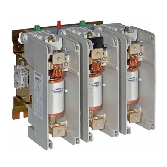
- Page 1 3TM 1-pole Vacuum contactor 4.15 kV - 6.9 kV OPERATING INSTRUCTIONS Order No.: 9229 0098 176 0- Version: 10.2018 en © Siemens AG 2018. All rights reserved.
-
Page 2: For Your Safety
For your safety Signal terms and Hazards are classified in accordance with ISO 3864-2 using the following keywords: definitions • DANGER, WARNING, or CAUTION, where there is a risk of personal injury • NOTE, where there is a risk of material damage. Hazards are classified and indicated in the operating instructions and on the vacuum contactor as follows: DANGER... -
Page 3: Table Of Contents
Contents For your safety ..............................2 List of abbreviations ............................4 Other applicable supplements for Operating Instructions 9229 0098 ..............4 Transport/storage/packaging ........................5 Transport ................................5 Scope of delivery ..............................5 Unpacking ................................5 Reuse of transport unit ............................6 Storage ................................ -
Page 4: List Of Abbreviations
List of abbreviations ANCE Asociación de Normalización y Certificación, A.C. (Association for Standardisation and Certification) ANSI American National Standard Institute American Wire Gauge BGBl Bundesgesetzblatt (German Federal Law Gazette) Close-Open Canadian Standards Association Deutsches Institut für Normung (German Institute for Standardisation) Dual in-line package Electromagnetic compatibility European standard... -
Page 5: Transport/Storage/Packaging
Major damage must be documented photographically. • Ensure that any damage to the transport unit is confirmed by the transport com- pany in writing Scope of delivery Delivery includes: • 3TM vacuum contactor • Operating instructions • Device-specific circuit diagrams • Connector (accessory pack) -
Page 6: Reuse Of Transport Unit
Transport/storage/packaging Transport to the Remove accessory pack and store safely in the packaging for later installation. installation site Due to the low weight, no lifting eyes are provided. The vacuum contactor can be lifted and transported without tools. The fastening eyelets (*) can be used for lifting with a crane. -
Page 7: Storage
Transport/storage/packaging Storage Note During transport and storage, the vacuum contactor must be in the following con- dition: • OPEN switching position • Unlatched condition (only if unlatching is available). Note Risk of corrosion damage if stored improperly! The vacuum contactor can be stored for up to a year in its transport unit if the stor- age conditions listed below are met. - Page 8 Transport/storage/packaging Blank page 9229 0098 176 0- 2019-01-09...
-
Page 9: General Information
The operating instructions are an integral part of the switching device and contain all information for commissioning and use. The basic version and all listed configurations of the vacuum contactors 3TM are type-tested devices as per IEC 62271-1 (see also “Standards”, on page 10) -
Page 10: Area Of Application
3TM vacuum contactors operate in continuous, periodic, and short-term operation. Suitable for high frequency of operation and unlimited on-time. Intended use Vacuum contactors 3TM are suitable for switching any type of alternating current cir- cuits under normal operating conditions, such as: •... -
Page 11: Type Approval As Per The German X-Ray Ordinance
General information Type approval as per the German X-Ray Ordinance The vacuum interrupters installed in the switching devices are type-approved as sources of interference radiation according to § 8 of the German X-Ray Ordinance and they comply with the requirements for sources of parasitic X-ray emitters ac- cording to Annex 2 No. - Page 12 General information Blank page 9229 0098 176 0- 2019-01-09...
-
Page 13: Description
Description Description Design The vacuum contactor is a 1-pole switching device consisting of: • the high-voltage section with vacuum interrupters, customer terminals and posi- tion indicator on the front side, • the low-voltage section with the solenoid actuator • the electronic controller for the solenoid actuator and shunt release •... - Page 14 Description 2 Base plate (mounting) 3 Vacuum interrupter 4 Upper terminal 5 Lower terminal 7 Pole shell 9 Mechanical closing latching with shunt release Y1 (optional) 10 Cover for closing latching (optional) 11 Shunt release Y1 (optional) 12 Push rod for manual unlatching (optional) 14 Unlatching (EMERGENCY STOP), manual (optional) 15 Draw bar for manual unlatching (optional) 21 Connector for supply voltage A1/A2...
- Page 15 The vacuum interrupter is actuated by a common solenoid actuator. This solenoid actuator has a very low holding capacity in continuous operation. The solenoid actuator and the shunt release of the vacuum contactor 3TM can be actuated with AC or DC.
- Page 16 Description Fig. 6 Terminals A1/A2 and optionally E1/E2 of the electronic controller The electronic controller also allows the configuration of additional closing and open- ing delays. If no configuration is selected, only the natural closing and opening time of the switching device is active. Configuration is done via a 6-pole DIP switch S2 on the electronics assembly (matrix, see Chapter “Configuring the controller”, p.
-
Page 17: Rating Plate
Mechanical stress Weight x Mechanical strain, values given for vibrations and Date of manufacture 08/18 shock Made in Germany y Weight z Date of manufacture Fig. 9 Example - rating plate for vacuum contactor 3TM 9229 0098 176 0- 2019-01-09... -
Page 18: Technical Data
Description Technical data Electrical data 4.15 4.15 Rated voltage U Rated frequency f 50-60 Rated operating current I (at ambient temperatures ranging from -40 °C to +70 °C) Thermal current I Rated lightning impulse withstand voltage U Rated short-duration power frequency withstand volt- age U phase-to-earth Fig. -
Page 19: Ambient Conditions
Description Auxiliary switch Protection class on the front side IP 20 Rated insulation level at pollution degree 3 Rated short-duration power frequency withstand voltage U Rated operating current I at rated voltage U AC 24 V Utilisation category AC 12 for alter- nating current AC 230 V Utilisation category AC 14 for alter-... -
Page 20: Installation Altitudes
The installation altitude for the vacuum contactor is set at the factory according to the ordering option. As standard, 3TM vacuum contactors can be used at -1250 m to +2000 m. For high- er operation heights, a configuration from 2000 m to 5000 m can be ordered. -
Page 21: Dimensional Drawings
Depth mounting holes plate Mass and lower Rated current terminals 4.15 kV - 450 A 6.9 kV with 4NC and 4NO Fig. 18 Rated data of 3TM vacuum contactor, with auxiliary switches 4NO + 4NC 9229 0098 176 0- 2019-01-09... -
Page 22: Circuit Diagrams
Description Circuit diagrams Fig. 19 Example 110 V to 125 V, with auxiliary switches 4NO + 4NC - without closing latch Only terminals A1 and A2 are to be used. Terminals E1 and E2 are avail- able, but not assigned (de-energised). 9229 0098 176 0- 2019-01-09... - Page 23 Description Fig. 20 Example 110 V to 125 V, with auxiliary switches 4NO + 4NC - with mechanical closing latching and shunt release Y1 Terminals E1 and E2 are assigned in- dependent of A1 and A2. 9229 0098 176 0- 2019-01-09...
- Page 24 Description Fig. 21 Example 220 V to 240 V, with auxiliary switches 4NO + 4NC - without closing latch Only terminals A1 and A2 are to be used. Terminals E1 and E2 are avail- able, but not assigned (de-energised). 9229 0098 176 0- 2019-01-09...
- Page 25 Description Fig. 22 Example 220 V to 240 V, with auxiliary switches 4NO + 4NC - with mechanical closing latching and shunt release Y1 Terminals E1 and E2 are assigned in- dependent of A1 and A2. 9229 0098 176 0- 2019-01-09...
- Page 26 Description Blank page 9229 0098 176 0- 2019-01-09...
-
Page 27: Installation
Installation Installation DANGER Risk of injury! • Do not touch live parts! • When work is performed on the switchgear, it must be de-energised and earthed! • The work described in the following sections must only be performed when the switchgear has been de-energised: Take safety measures to prevent reclosing! Observe industrial safety regulations! Ensure that the vacuum contactor is mounted and commissioned only by... - Page 28 Installation Due to the special shape of the mounting holes on the 3TM vacuum contactor , it is possible to position it safely on loose, pre-assembled screws. Mount the 3TM vacuum contactor tension-free and torsion-free at the four specified mounting points (*) on a frame, wall, or on a withdrawable part.
- Page 29 Mounting the mechanical closing latching (optional) and manual unlatching (optional) If the 3TM vacuum contactor 3is prepared for backfit, the mechanical closing latch- ing with shunt release Y1 and manual unlatching can be mounted in accordance with the supplied assembly drawing.
- Page 30 Installation Removing the side plate • Remove the screws on the side plate (33) and remove the side plate (see Fig. 28). Fig. 28 Removing the side plate Fig. 29 Mounting the side plate Auxiliary switch Side plate Switching lever cam Switching lever for auxiliary switch Recess in switching lever Mounting the side plate...
- Page 31 Installation • without exceeding the permissible connector cross-sections • under consideration of the potential voltage drops due to long cables • with cables routed in an S configuration • using suitable fastening elements to secure the cables If long cables are necessary for control circuits, malfunctions can occur on closing or opening under certain conditions.
- Page 32 Installation Functional check with ap- When low voltage is applied, the release, closing, and opening of the vacuum con- plied low voltage tactor can be checked. DANGER Danger to life – high voltage! Closing without safety precautions can result in death or serious injury. Test the vacuum contactor in the switchbay with high voltage applied only after faultless functioning has been ascertained (see "Commissioning", p.
- Page 33 Installation Preparing contact surfaces Note Clean silver-plated contact areas with a cloth; do not brush. Different connection materials (AI/Cu) must not be cleaned with the same clean- ing tools. Silver-plated parts must not be bolted to aluminium bars! Use a steel brush to carefully brush (cross-wise) the contact surfaces of the cable lugs or busbars until they are metallic bright and wipe off any residue using a clean cloth.
- Page 34 Installation Mounting busbars Adjust the busbars in such a way that, before fastening, they lie flat easily and fit the holes on the contact surfaces of the upper and lower terminal. Fig. 36 Busbars mounted at an angle Fig. 37 Busbars mounted in a straight position Corresponding to the rated current strength, use M10 screws and nuts - strength class 8.8 - and the appropriate spring elements and washers for connection of the...
-
Page 35: Operation
Operation Operation DANGER Danger to life due to electric shock! Electric shock can result in death, serious injury, or considerable material dam- age. • Do not touch live parts! • Ensure that the vacuum contactor is operated only by qualified personnel who are familiar with the operating instructions and observe the warning notices! •... -
Page 36: Troubleshooting
WARNING Do not commission the vacuum contactor if there are malfunctions. If the malfunctions or damage cannot be remedied, contact a sales representative or Siemens Service and, if necessary, send back the vacuum contactor in the original packaging. Troubleshooting Incident... -
Page 37: Maintenance
Measurement of conductance of auxiliary switch contacts. Checking the switching Reliable switching of the 3TM vacuum contactor is only ensured if the switching stroke of vacuum stroke of the vacuum interrupters is not below the minimum of 3.5 mm and does not interrupters exceed the maximum of 7.5 mm. - Page 38 Maintenance Limit Fig. 38 OPEN switch position Fig. 39 CLOSED switch position Limit: a - b = min. ≥ 3.5 mm or max. ≤ 7.5 mm OPEN switch position CLOSED switch position Adjusting the switching Torsional loading of the draw bar (40) of the vacuum interrupters (3) must be pre- stroke of vacuum vented.
-
Page 39: Accessories And Spare Parts
Maintenance 1.25 mm. If the value is above the limit - turn the adjusting nut (42) counter-clockwise at least one turn, approx. 1.5 mm higher. • Use the open-end spanner to prevent the adjusting nut (42) from turning and securely tighten the locking nut (41). •... - Page 40 Maintenance Accessory/spare part Order number Comment Mechanical closing latching with shunt release Y1 Release voltage DC 24 V 3TX5903-0AB0 DC 30 V 3TX5903-0AC0 DC 48 V 3TX5903-0AD0 DC 60 V 3TX5903-0AE0 DC 110 V 3TX5903-0AF0 DC 125 V 3TX5903-0AG0 DC 220 V 3TX5903-0AH0 DC 250 V 3TX5903-0AJ0...
- Page 41 Maintenance Replacing the electronic controller CAUTION Material damage caused by electrostatic discharge to the electronic con- troller Electrostatic discharge can cause material damage to the electronic controller and restrict its functionality. To prevent damage to electronic components, discharge any existing electrostat- ic charges on hands or tools by touching grounded surfaces prior to touching electronic components and before removing the connector plugs.
- Page 42 Despite this, the MLFB on the rating plate must then be changed. Line g, s to v, see “Example - rating plate for vacuum contactor 3TM”, page 17, Fig. 9. OPEN...
-
Page 43: Manufacturer's Product Liability
If the packaging is no longer needed, it can be fully recycled. Hazardous substances When delivered by Siemens, the product does not contain any hazardous substanc- es within the scope of the Hazardous Substances Ordnance applicable to the terri- tory of the Federal Republic of Germany. The switching devices are free from asbestos, halogens, and lead. - Page 44 Maintenance Blank page 9229 0098 176 0- 2019-01-09...
-
Page 45: Index
Index Index – Accessories available for order ......40 Pole shell ............13 Altitude correction factor ........20 Position indicator ........... 13 Ambient conditions ..........19 Power loss Areas of application ..........10 holding mode ........... 18 Auxiliary switch ........13 shunt release ........... - Page 46 Index Blank page 9229 0098 176 0- 2019-01-09...
-
Page 47: Central Legend
Central legend Central legend 1 Vacuum contactor 2 Base plate 3 Vacuum interrupter 4 Upper terminal 5 Lower terminal 6 Position indicator OPEN-CLOSED 7 Pole shell 8 Rating plate 9 Mechanical closing latching with shunt release Y1 10 Cover of closing latching 11 Shunt release Y1 12 Push rod for manual unlatching 13 Coupling point for customer connection... - Page 48 Published by Siemens AG Energy Management Division Medium Voltages & Systems Schaltwerk Berlin Nonnendammallee 104 13629 Berlin Germany...
Need help?
Do you have a question about the 3TM and is the answer not in the manual?
Questions and answers