
Subscribe to Our Youtube Channel
Related Manuals for abc 422197


Summary of Contents for abc 422197
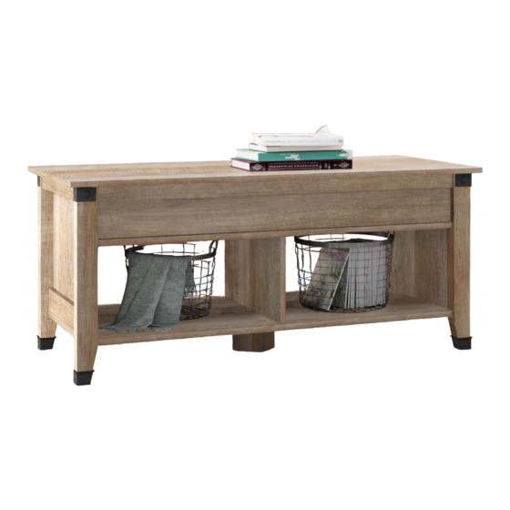
- Page 1 Guaranteed to hold other beverages, too. Lift-Top Coff ee Table NOTE: THIS INSTRUCTION BOOKLET CONTAINS IMPORTANT SAFETY INFORMATION. PLEASE READ AND KEEP FOR FUTURE REFERENCE. English pg 1-19 Français pg 20-22 Español pg 23-25 Purchased: __________________...
- Page 2 Table of Contents Assembly Tools Required Part Identifi cation No. 2 Phillips Screwdriver Tip Shown Actual Size Hardware Identifi cation Assembly Steps 5-19 Hammer Not actual size Français 20-22 Español 23-25 Short Screwdriver Safety Warranty Adjustable Wrench Skip the power trip. This time.
- Page 3 Part Identifi cation...
- Page 4 Hardware Identifi cation å Screws are shown actual size. You may receive extra hardware with your unit. ® 7F TWIST-LOCK FASTENER - 10 HIDDEN CAM - 8 CAM SCREW -8 WOOD DOWEL - 8 23M LIFT TABLE SUPPORT BRACKET - 2 BUMPER - 6 WASHER - 8 MECHANISM SET - 1...
- Page 5 Step 1 Assemble your unit on a carpeted fl oor or on the empty å carton to avoid scratching your unit or the fl oor. To begin assembly, push a TWIST-LOCK® å FASTENER (7F) into the large holes in the SHELF (E) and FRONT PANELS (J).
- Page 6 Step 2 Turn eight CAM SCREWS (8F) into exact holes shown in å the LEGS (F and G). Push eight HIDDEN CAMS (1F) into the exact holes shown å in the ENDS (A and B). (8 used) Arrow (8 used) Arrow Arrow Hole...
- Page 7 Step 3 Fasten the SHELF (E) to the FRONT PANELS (J). Use å eight BLACK 1-15/16" FLAT HEAD SCREWS (113S). Remember: Righty tighty. NOTE: You may want to start each SCREW a few turns å Lefty loosey. before completely tightening any of them. 113S BLACK 1-15/16"...
- Page 8 Step 4 Fasten the LEFT END (B) to the SHELF (E) and FRONT å How to use the TWIST-LOCK® FASTENER PANELS (J). Tighten fi ve TWIST-LOCK® FASTENERS. 1. Insert the dowel end of the FASTENER into the hole of the adjoining part. Fasten the UPRIGHT (D) to the SHELF (E).
- Page 9 Step 5 First, fi ll the exact holes shown in the BOTTOM (C) 1/4 to å 1/2 full with GLUE (54M). Then, insert four WOOD DOWELS (15F) into the holes. Wipe away the excess GLUE. Now, fi ll the holes in the LEFT END (B) 1/4 to 1/2 full with å...
- Page 10 Step 6 NOTE: You may want to use a SHORT SCREWDRIVER in this step. å Fill the holes in the RIGHT END (A) 1/4 to 1/2 full with GLUE (54M). å Fasten the RIGHT END (A) to the SHELF (E) and FRONT å...
- Page 11 Step 7 Turn four BLACK 9/16" FLAT HEAD SCREWS (32S) into the ENDS (A and B) until the shoulders of the SCREWS rest on å the surfaces of the ENDS. NOTE: Do not overtighten the SCREWS. å Slide the END MOLDINGS (K) onto the ENDS (A and B). Line up the grooves in the MOLDINGS over the heads of the å...
- Page 12 Step 8 Carefully turn your unit onto its top edges. å First, fi ll the holes in the LEGS (F and G) 1/4 to 1/2 full with å GLUE (54M). Then, insert the WOOD DOWELS (15F) into the holes. Wipe away the excess GLUE. Now, fi...
- Page 13 Step 9 Carefully stand your unit upright. å Pro Tip: Lift with your Tighten the four HIDDEN CAMS in the ENDS (A and B) at å legs. And, you know, this time. your arms. Center a SCREW COVER (20P) over the head of each å...
- Page 14 Step 10 Fasten the LIFT TABLE MECHANISMS (23M) to the TOP (I). å Use six BLACK 9/16" LARGE HEAD SCREWS (1S). NOTE: Be sure to position the LIFT TABLE MECHANISMS on å the TOP exactly as shown. Push six BUMPERS (2M) into the holes in the TOP (I). å...
- Page 15 Step 11 Fasten the SUPPORT BRACKETS (37G) to the LIFT å TABLE MECHANISMS (23M). Use four WASHERS (13M), NUTS (24M), and BLACK 3/4" MACHINE SCREWS (92S). NOTE: Use the adjustable wrench in this step. å BLACK 3/4" MACHINE SCREW (4 used in this step)
- Page 16 Step 12 IMPORTANT: You will need someone's help in this step. å Fasten the TOP (I) to the ENDS (A and B). Use ten BLACK 9/16" LARGE HEAD SCREWS (1S) through the LIFT TABLE å MECHANISMS (23M) and into the holes in the ENDS. NOTE: Be careful when lining up the holes in the MECHANISMS with the holes in the ENDS as to not damage any parts.
- Page 17 Step 13 Fasten the TOP (I) to the ENDS (A and B). Use two å BUSHINGS (91M) and two BLACK 3/4" PAN HEAD SCREWS (85S) through the exact holes shown in the LIFT TABLE MECHANISMS (23M) and into the holes in the ENDS. NOTE: Do not overtighten the SCREWS (85S).
- Page 18 Step 14 Fasten the STRETCHER (H) to the SUPPORT BRACKETS (37G) on å the LIFT TABLE MECHANISMS (23M). Use four WASHERS (13M), If you're doing this to NUTS (24M), and BLACK 1-1/4" MACHINE SCREWS (93S). help a friend, don't leave without a bite. NOTE: Use the adjustable wrench in this step.
- Page 19 Step 15 IMPORTANT: Do not place valuables in the storage space. å NOTE: Please read the back pages of the instruction booklet for important safety information. å This completes assembly. Clean with your favorite furniture polish or a damp cloth. Wipe dry. å...
- Page 20 Modèle 422197 Table basse à dessus relevable Utilisez les instructions d’ a ssemblage en français avec les NOUS SOMMES LA POUR VOUS AIDER! schémas étape par étape du manuel d’instruction en anglais. Nous faisons de notre mieux pour nous assurer que votre meuble Chaque étape en français correspond à...
- Page 21 ÉTAPE 1 ÉTAPE 6 Ne pas serrer les FIXATIONS TWIST-LOCK® à cette étape. Attention: Examiner bien les pièces avant d'assembler. Il est diffi cile de séparer des pièces une fois encollées. Assembler l'élément sur un sol à moquette ou sur le carton vide pour éviter d'endommager l'élément ou le sol.
- Page 22 ÉTAPE 9 ÉTAPE 13 Relever, avec précaution, l'élément dans sa position verticale. Fixer le DESSUS (I) aux EXTRÉMITÉS (A et B). Utiliser deux MANCHONS (91M) et deux VIS TÊTE GOUTTE DE SUIF 19 mm Serrer les quatre EXCENTRIQUES ESCAMOTABLES sur les NOIRES (85S) à...
- Page 23 Modelo 422197 Mesita para café con tapa superior Use estas instrucciones de ensamblaje en español junto con las ESTAMOS AQUI PARA AYUDAR! fi guras paso-a-paso provistas en el folleto inglés. Cada paso Tratamos de asegurar que su mueble llega en condición excelente.
- Page 24 PASO 1 PASO 6 No apriete los SUJETADORES TWIST-LOCK® en este paso. Precaución: Revise las partes cuidadosamente antes de ensamblar. La separación de las piezas ya pegadas es muy difícil. Ensamble la unidad sobre un piso alfombrado o sobre el cartón vacío para evitar rayar la unidad o el piso.
- Page 25 PASO 9 PASO 13 Cuidadosamente ponga la unidad en posición vertical. Fije el PANEL SUPERIOR (I) a los EXTREMOS (A y B). Utilice dos FORROS (91M) y dos TORNILLOS NEGROS DE Apriete en este momento los cuatro EXCÉNTRICOS CABEZA REDONDA de 19 mm (85S) a través de los agujeros ESCONDIDOS en los EXTREMOS (A y B).
- Page 26 WARNING Please use your furniture correctly and safely. Improper use can cause safety hazards, or damage to your furniture or household items. Carefully read the following chart. Look out for: What can happen: How to avoid the problem: • Overloaded shelves. •...
- Page 27 5-YEAR LIMITED WARRANTY 1. The company provides limited warranty coverage to the original purchaser of this 4. This Warranty applies only to warranted defects that fi rst arise and are reported product for a period of fi ve years from the date of purchase against defects in within the warranty coverage period.
Need help?
Do you have a question about the 422197 and is the answer not in the manual?
Questions and answers