
Summary of Contents for Igema BTU-100
- Page 1 Brake Test Unit BTU-100 Edition 06/2021 D-04-B-51602-EN-00 INSTALLATION AND OPERATING INSTRUCTIONS...
- Page 2 Product philosophy Thank you for placing your trust in IGEMA and deciding in favour of one of our high-quality products. For more than 100 years, measuring and control systems have been developed, produced and sold worldwide under the IGEMA brand name.
-
Page 3: Table Of Contents
Table of Contents Important safety instructions ................5 1.1 Symbols used in these instructions ..............5 1.2 General safety instructions ................6 1.2.1 Avoidance of risks to persons and property ..........6 1.2.2 Limitations of use ..................7 1.2.3 Avoidance of risks and damage ..............7 1.3 Exclusion of liability ................... - Page 4 Table of Contents 6.4 Brake TEST ....................13 6.5 Static TEST (stat. TEST) ................. 14 6.6 Zero calibration ....................15 6.7 Pressure adjustment in the supply line ............15 6.8 Measuring point "control pressure" ..............15 6.9 Settings ......................15 6.10 Info ........................
-
Page 5: Important Safety Instructions
Unqualified persons must not be assigned the above tasks! IGEMA GmbH accepts no liability for damage to property or personal injury caused by unqualified persons or by failure to observe these installation and operating instructions. If no sufficiently qualified person can be found, IGEMA GmbH can be commissioned with the installation/maintenance. -
Page 6: General Safety Instructions
This symbol and signal word refer to a potentially hazardous situation which could result in personal injury, property and environmental damage if ignored. Caution This symbol and signal word refer to a potentially hazardous situation which could result in damage to the equipment if ignored. -
Page 7: Limitations Of Use
IGEMA GmbH Mess- und Regelsysteme will assume no liability if the above regulations, instructions and safety precautions are not observed and followed. If they are not expressly listed in the installation and operating instructions, changes to an IGEMA device are carried out at the risk of the user. -
Page 8: Introduction
Introduction The simulation device "Brake Test Unit" (hereinafter referred to as BTU) has been developed for testing the brakes of trailers with pneumatic braking systems. The BTU is coupled into the pneumatic brake line between the tractor and trailer. The desired brake pressure for the towed vehicle can be set and controlled electronically using BTU, independent of the tractor. -
Page 9: Scope Of Delivery
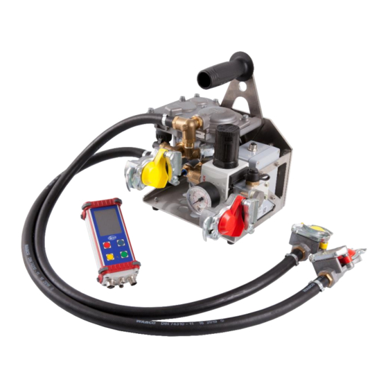
3.1 Scope of delivery Number Description Index Control unit (hand-held) Pneumatic unit Connection cable control unit <-> pneumatic unit 5m Power supply cable 2m External start/stop button 1.5m VBox connection cable 1.5m Adapter cable power supply DIN9680 <-> standard vehicle plug 0.2m Protection and transport case Hand-held/Control unit and accessories Design 4.1 Control unit (a) -
Page 10: Pneumatic Unit (B)
4.2 Pneumatic unit (b) Index Description Control pressure input (Yellow) Carrying handle Control valve Control pressure output (Yellow) Pressure switch 0.3/0.5/0.8 bar (30, 50, 80 kPa) Pressure gauge for supply pressure outlet Supply pressure outlet (Red) Test connection M16x1.5 external thread Electronics box ECU Cable connection to the control unit Precision pressure regulator for supply pressure outlet... -
Page 11: Commissioning
Commissioning 5.1 Power supply The device is designed for a voltage of 12-24V DC. A DIN 9680 plug and a standard vehicle plug (in the form of an adapter cable) are available as connection options. 5.2 Connection diagram Control unit (a) Power supply 12-24V DC Standard vehicle plug... -
Page 12: Operation
Operation 6.1 Key configuration The interactive display shows the function of each key. The display and keys are configured as follows: 6.2 Start-up After commissioning, the manufacturer's logo appears on the display (1) for approx. 3 seconds. Afterwards the customer's logo with the following information is displayed: Last service Serial number This information can also be displayed later under the menu item "Info". -
Page 13: Brake Test
6.4 Brake TEST Under "brake-TEST", a predefined pressure is applied to the trailer brake line. The display (1) shows the set target brake pressure under "p target" and the current pressure in the trailer brake line under "p actual". The values have the unit [kPa]. The operating status of the device is listed under "Status". -
Page 14: Static Test (Stat. Test)
6.5 Static TEST (stat. TEST) The static TEST “stat. TEST“ is designed for use with roller test bench. The difference between mode “brake TEST“ and this one is, that the target pressure can be changed in run mode. The ... -
Page 15: Zero Calibration
6.6 Zero calibration The internal pressure sensor should be calibrated once daily before use. Zero calibration is used for this purpose. The sub-item "Zero calibration" contains the following options: Type Start 0kPa The adjustment type is factory set to "one point" and cannot be changed in v1.00. Perform one-point zero calibration: First, please make sure that the control line is de-energised. -
Page 16: Info
6.10 Info Under "Info" you can safely display device information. It includes the following: ECU firmware version (pneumatic unit) HH firmware version (control unit) Serial number Last service External start/stop button The device has an external start/stop button connection. This can be used to start or stop the braking process. -
Page 17: Alert: "Beware: Pressure Switch Triggered
8.2 Alert: "Beware: Pressure switch triggered" If a pressure of > 0.3/0.5/0.8 bar (30.50.80 kPa) is applied to the control line, the locking function is interrupted in the "Attention" and "Run" status. This means that during operation the active control is deactivated and the brake pressure from the towing vehicle is available in the control line. -
Page 18: Menu Layout
Menu layout 3 seconds External start/stop button External start/stop button Enter Atten. Start Exit Blue/ Yellow Rec ON/OFF Target pressure +/- All buttons... - Page 19 External start/stop button External start/stop button Enter Atten. Start Exit Blue/ Yellow Rec ON/OFF Target pressure +/- Target pressure +/- All buttons Enter Down Enter Exit Exit Enter Down Exit Language Rec ON / OFF Exit...
- Page 20 Enter Exit...
-
Page 21: Technical Data
10. Technical data Voltage 12-24 V DC Power 33 W Max. operating pressure 1000 kPa... -
Page 22: Declaration Of Conformity
11. Declaration of conformity...
Need help?
Do you have a question about the BTU-100 and is the answer not in the manual?
Questions and answers