Advertisement
Available languages
Available languages
Quick Links
Advertisement

Related Manuals for FILL-RITE TS20A


Summary of Contents for FILL-RITE TS20A
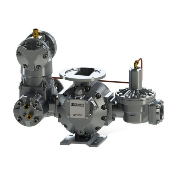
- Page 1 Electronic Bulk / Tank Meter for LPG with 2 Thermo Wells Installation, Operation & Parts Manual TS20A LPG Models mdi - Manufacturers Distributor Inc. | Phone: (813) 241 - 4900 | Fax: (813) 571 - 0422 | www.FillRitePumpSales.com | Sales@FillRitePumpSales.com...
- Page 2 INDEX Safety Procedures Installation & Operations Torque & Wrench Chart Meter Maintenance 9-15 Disassembly Flow Meter Inlet Check Valve Strainer Vapor Eliminator Differential Valve Parts List: Inlet Check Valve Vapor Eliminator Differential Valve Security Valve Meter & Strainer SCL (Pulser Assembly) Meter calibration 18-19 Troubleshooting...
- Page 3 S A F E T Y P R O C E D U R E S This manual provides warnings and procedures that are intended to inform the owner/operator of the hazards present when using the Tuthill Transfer Systems, TUTHILL meters and other products. The reading of these warnings and the avoidance of such hazards is strictly in the hands of the owner/operator of the equipment.
- Page 4 The meter must always be securely bolted to a platform or ing meter, please refer to: supporting member, regardless of the mounting position. Page 6 for TS20A with EMR register Never “hang” a meter on the connecting pipe. Position the meter with service in mind. Provide ample work space.
-
Page 5: Torque Chart
Installation & Operation continued Every meter should be calibrated under actual service and Start-Up: installation conditions. Follow your local Weights and Measures recommendations. Fill the system slowly to avoid operation on air or vapor. This can be accomplished in the following manner: Provide a means of conveniently diverting liquid for calibra- tion purposes. - Page 6 Installation & Operation continued Where the TS20A is used in commercial or retail LPG , the meter used with registers available through Tuthill. It can of flow meter will be shown in manufacturer wiring diagram. course also be used with many other registers.
- Page 7 Installation & Operation continued EL0304 to MCR-05 Register Pulser cable plugs into: J1 on EL0304 Signal output cable is connected to TB1 mdi - Manufacturers Distributor Inc. | Phone: (813) 241 - 4900 | Fax: (813) 571 - 0422 | www.FillRitePumpSales.com | Sales@FillRitePumpSales.com...
- Page 8 Installation & Operation continued Theory of Operation; When properly installed, this line must permit free flow in The TUTHILL meters LPG metering system combines an either direction. If the vent line is closed the meter will not oval gear positive displacement meter, differential valve, function, as the differential valve will not open.
-
Page 9: Flow Meter Maintenance
Flow Meter Maintenance Danger!! Danger!! Danger!! Relieve all internal pressure before servicing. Line pressure must be 0.0 PSI Serious injury or death from fire or explosion could result from maintenance of an improperly de-pressurized and evacuated system. Preparing for Service: Removing flange seals: When removing the flange assembly, always carefully remove the O-ring seal. - Page 10 Flow Meter Maintenance Danger!! Danger!! Danger!! Relieve all internal pressure before servicing. Line pressure must be 0.0 PSI Serious injury or death from fire or explosion could result from maintenance of an improperly de-pressurized and evacuated system. Meter Disassembly: (refer to diagram on page 16). ...
- Page 11 Flow Meter Maintenance Back Check Valve Service (see pages 12 and 16): Re-assemble the meter in the opposite direction making Disconnect the inlet piping from the meter assembly at sure all bolts are torqued to the proper specifications. the differential valve outlet flange.
- Page 12 Flow Meter Maintenance KITTSDS20 Diaphragm Seal Kit Item # Qty Description O-Ring, Buna O-Ring, Buna Backup Washer, 2" Differential Diaphragm, 2" Differential KITTSDS20 VP1950 Backcheck Assembly Item # Qty Description Body, 2" Backcheck, Finish Coated Piston, 2" Backcheck, Anodized O-Ring, Buna Screw, 10-32 X 3/8 SHCS Poppet, 2"...
- Page 13 Flow Meter Maintenance RKAE20 Repair Kit Air Eliminator Float Assembly w/Reeds KITTAE20 Air Eliminator Seal Kit, LPG Item # Qty Description Item # Qty Description 1 Mounting Block Reed 2 O-Ring, Buna* 12 Screw, 5/16-18 X 1 SHCS 2 Ring, Retaining 2 Plate, Oriface Assembly* 1 Relief Valve, Hydrostatic 2 Reed, Oriface...
- Page 14 Flow Meter Maintenance DV1200 Differential Valve Item # Qty Description Valve, 2" Differential Cover, 2" Differential Valve O-Ring Retainer, Dif. Bal Valve Seat Retainer, Dif. Val. Diaphragm Locking Screw Diaphragm, 2" Differential Backup Washer, 2" Differential Screw, 10-32 X 5/8" SHCS SS 12 Screw, 5/16-18 X 1-1/4"...
- Page 15 Flow Meter Maintenance KITTSSSV20 Security Valve Kit KITTUBV3, TS20A Tubing Kit, SEC. VLV., LPG Item # Qty Description Bracket, Security Valve, LPG Anodized Valve, Security, LPG Screw, 1/4-20 X 3/8"SHCS Fitting, 1/4" Tube X 1/4" NPT, M Elbow, LPG Fitting, 1/4" Tube X 1/4" NPT, Male, LPG...
-
Page 16: Exploded View
Exploded View mdi - Manufacturers Distributor Inc. | Phone: (813) 241 - 4900 | Fax: (813) 571 - 0422 | www.FillRitePumpSales.com | Sales@FillRitePumpSales.com... -
Page 17: Troubleshooting
Trouble Shooting Problem Probable Cause and Solution Leakage from seal cover. Seal has been damaged due to shock Cover bolts have not been tightened sufficiently Replace seal and /or re-torque bolts Product flows through meter but the regis- ... - Page 18 SCL & Pulser Assembly If in the minus (-) position, an increase in the S3 and (Scaler/Calibrator/Linearizer) S4 switch settings will decrease the pulse output. A decrease in pulse output will increase the volume in Description: Tuthill SCL is a small electronic device de- a prover vessel.
-
Page 19: Flow Meter Calibration
Flow Meter Calibration Activate the Reset push button switch to enter the new data. NOTE: If S2 is in the plus (+) position, and S3 and S4 are at 15 as an example, then moving the posi tion of S3 and S4 to 00 will provide a (0.03 x 15) =.45% increase in the prover volume. - Page 20 NOTES DC001337-000 Rev. 1 mdi - Manufacturers Distributor Inc. | Phone: (813) 241 - 4900 | Fax: (813) 571 - 0422 | www.FillRitePumpSales.com | Sales@FillRitePumpSales.com...
- Page 21 GLP con 2 pozos termométricos Manual de instalación, operación y piezas Modelos TS20A GLP mdi - Manufacturers Distributor Inc. | Phone: (813) 241 - 4900 | Fax: (813) 571 - 0422 | www.FillRitePumpSales.com | Sales@FillRitePumpSales.com...
- Page 22 ÍNDICE Procedimientos de seguridad Instalación y funcionamiento Tabla de llaves y torsión Mantenimiento del medidor 9-15 Desmontaje Medidor de flujo Válvula de retención de entrada Filtro Eliminador de vapor Válvula diferencial Lista de piezas: Válvula de retención de entrada Eliminador de vapor Válvula diferencial Válvula de seguridad Medidor y filtro...
- Page 23 PROCEDIMIENTOS DE SEGURIDAD Este manual proporciona advertencias y procedimientos diseñados para informar al propietario u operador, acerca de los peligros presentes al utilizar los medidores TUTHILL y otros productos de Tuthill Transfer Systems. La lectura de estas advertencias y la prevención de dichos peligros están estrictamente en las manos del propietario u operador del equipo.
-
Page 24: Instalación Y Funcionamiento
Nunca “cuelgue” un medidor en la tubería dispensación “autónomo”, consulte: de conexión. Pagina 6 para TS20A con registrador EMR Ubique el medidor considerando el servicio. Proporcione un amplio espacio de trabajo. El retiro de las cubiertas puede ser difícil cuando no se dispone de espacio de trabajo. Proporcione siempre una plataforma o soporte para el montaje del medidor. - Page 25 Instalación y funcionamiento (continuación) Arranque: Cada medidor se debe calibrar conforme a las condiciones de instalación y servicio actuales. Siga las recomendaciones de Llene lentamente el sistema para evitar el funcionamiento en pesos y medidas locales. aire o vapor. Esto se puede lograr de la siguiente manera: Proporcione un medio para desviar fácilmente el líquido para •...
- Page 26 Instalación y funcionamiento (continuación) Cuando la unidad TS20A se use en GLP comercial o para la En los diagramas de cableado de estas 2 páginas, se muestra venta al detalle, el medidor de flujo se mostrará en el diagrama el medidor de flujo con registradores que están disponibles a de cableado del fabricante.
- Page 27 Instalación y funcionamiento (continuación) NEGRO COMÚN ROJO +5 V CC VERDE SEÑAL DE CANAL A CLARO SEÑAL DE CANAL B AZUL NO SE USA NO SE USA SEÑAL A SEÑAL B EL0304 a registrador MCR-05 • El cable del generador de impulsos se conecta en: •...
- Page 28 Instalación y funcionamiento (continuación) Teoría de funcionamiento; para el vapor del tanque de suministro y, normalmente, no se deben unir a otras tuberías de retorno de vapor o tuberías de El sistema de medición de GLP del medidor TUTHILL combina derivación de la bomba.
- Page 29 Mantenimiento del medidor de flujo ¡Peligro! ¡Peligro! ¡Peligro! Alivie toda la presión interna antes de realizar cualquier tarea de mantenimiento. La presión de la tubería debe ser de 0 barias. Si se realiza el mantenimiento de un sistema incorrectamente evacuado y despresurizado, se pueden producir lesiones graves o la muerte por incendios o explosiones.
- Page 30 Mantenimiento del medidor de flujo (continuación) ¡Peligro! ¡Peligro! ¡Peligro! Alivie toda la presión interna antes de realizar cualquier tarea de mantenimiento. La presión de la tubería debe ser de 0 barias. Si se realiza el mantenimiento de un sistema incorrectamente evacuado y despresurizado, se pueden producir lesiones graves o la muerte por incendios o explosiones.
- Page 31 Mantenimiento del medidor de flujo (continuación) • Inspeccione todos los sellos y reemplácelos si están Mantenimiento de la válvula de retención de entrada dañados o quebradizos. (consulte las páginas 12 y 16): • • Vuelva a montar el medidor en la dirección opuesta y Desconecte las tuberías de entrada del conjunto de asegúrese de que todos los pernos se aprieten conforme a medidor, en el reborde de salida de la válvula diferencial.
- Page 32 Mantenimiento del medidor de flujo (continuación) APLIQUE SELLADOR DE JUNTAS PERMATEX 98H Juego de sello de diafragma KITTSDS20 HIGH TACK EN AMBOS LADOS DEL DIAFRAGMA, EN UN ANCHO APROXIMADO DE 13 MM N.° de Cant. Descripción elemento ALREDEDOR DEL ORIFICIO CENTRAL DURANTE EL MONTAJE Junta tórica, Buna Junta tórica, Buna Arandela de refuerzo, diferencial de 5,1 cm Diafragma, diferencial de 5,1 cm...
- Page 33 Mantenimiento del medidor de flujo (continuación) Conjunto de flotador de eliminador de aire del juego de repuesto RKAE20 con lengüetas KITTAE20 Eliminador de Aire Kit de juntas, LPG N.° de N.° de Cant. Descripción Cant. Descripción elemento elemento Junta tórica, Buna* Lengüeta del bloque de montaje Tornillo de cabeza hueca, 5-16-18 x 1 Anillo, de retención Placa, conjunto perforado* Válvula de alivio, hidrostática...
- Page 34 Mantenimiento del medidor de flujo (continuación) Juego de válvula diferencial DV1200 N.° de Cant. Descripción elemento Válvula, diferencial de 5,1 cm Cubierta, válvula diferencial de 5,1 cm Sujetador de junta tórica, válvula diferencial Sujetador de asiento de válvula, válvula diferencial Tornillo de fijación del diafragma Diafragma, diferencial de 5,1 cm Arandela de refuerzo, diferencial de 5,1 cm Tornillo de cabeza hueca, 10-32 x 5/8", acero...
- Page 35 Conector, tubo de 1/4" x 1/4" NPT, codo macho, GLP Conector, tubo de 1/4" x 1/4" NPT, macho, GLP Conjunto de tubos, TS20A, válvula de seguridad, eliminador de aire, GLP* Conjunto de tubos, TS20A, válvula de seguridad, medidor, GLP* Conjunto de tubos, TS20A, válvula de seguridad, difusor, GLP* Tornillo de cabeza hueca, 5/16-18 x 1,25", acero inoxidable...
- Page 36 Vista despiezada mdi - Manufacturers Distributor Inc. | Phone: (813) 241 - 4900 | Fax: (813) 571 - 0422 | www.FillRitePumpSales.com | Sales@FillRitePumpSales.com...
-
Page 37: Solución De Problemas
Solución de problemas Problema Causa probable y solución • El sello se dañó debido a los golpes. Fugas desde la cubierta del sello • Los pernos de la cubierta no se apretaron lo suficientemente. • Reemplace el sello o vuelva a apretar los pernos. •... - Page 38 SCL y conjunto de generador de impulsos INTERRUPTORES: (contador de impulsos/calibrador/linearizador) Descripción: SCL de Tuthill es un pequeño dispositivo S1 : Siempre deben estar en su posición definida. electrónico diseñado para proporcionar la función de un S2 : Se usa en conjunto con S3 y S4. contador de impulsos, un calibrador electrónico.
- Page 39 Calibración del medidor de flujo Active el interruptor con el botón pulsador Reset (Restablecer) para ingresar la nueva configuración del programa. Vuelva a probar el medidor de flujo. • Para aumentar el volumen en el recipiente del calibrador, coloque el interruptor S2 en la posición (-) negativa, y fije S3 y S4 en la configuración correcta para ajustar la salida.
- Page 40 NOTAS DC001337-000 Rev. 1 mdi - Manufacturers Distributor Inc. | Phone: (813) 241 - 4900 | Fax: (813) 571 - 0422 | www.FillRitePumpSales.com | Sales@FillRitePumpSales.com...
Need help?
Do you have a question about the TS20A and is the answer not in the manual?
Questions and answers