Sign In
Upload
Download
Table of Contents
Contents
Add to my manuals
Delete from my manuals
Share
URL of this page:
HTML Link:
Bookmark this page
Add
Manual will be automatically added to "My Manuals"
Print this page
×
Bookmark added
×
Added to my manuals
Manuals
Brands
Opera Manuals
Door locks
OUVERTURE EXIT
Quick start manual
Opera OUVERTURE EXIT Quick Start Manual
Electric handle
Hide thumbs
Also See for OUVERTURE EXIT
:
Manual
(13 pages)
1
2
3
4
5
6
7
8
9
10
11
12
Table Of Contents
13
page
of
13
Go
/
13
Contents
Table of Contents
Bookmarks
Table of Contents
Technical Specifications
Installation
Mode of Operation
Cylinder Replacement
Installation Examples
Connecting Diagram
Advertisement
Quick Links
Download this manual
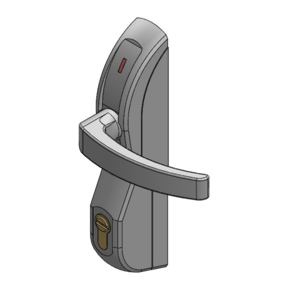
ELECTRIC HANDLE
"OUVERTURE EXIT"
Table of
Contents
Previous
Page
Next
Page
1
2
3
4
5
Advertisement
Table of Contents
Need help?
Do you have a question about the OUVERTURE EXIT and is the answer not in the manual?
Ask a question
Questions and answers
Related Manuals for Opera OUVERTURE EXIT
Locks Opera SMART TRIM Series Manual
Electric handle (13 pages)
Door locks Opera 13700 Installation Instruction
Electromagnetic lock (indoor series) (4 pages)
Door locks Opera ARCA SLIDE Installation Instructions Manual
(9 pages)
Door locks Opera 40600 Manual
Electric handle (12 pages)
Door locks Opera ARCA KEY SLIDE 23822 Mounting Instructions
(4 pages)
This manual is also suitable for:
40620
40621
40820
40821
Table of Contents
Print
Rename the bookmark
Delete bookmark?
Delete from my manuals?
Login
Sign In
OR
Sign in with Facebook
Sign in with Google
Upload manual
Upload from disk
Upload from URL


Need help?
Do you have a question about the OUVERTURE EXIT and is the answer not in the manual?
Questions and answers