Advertisement
Advertisement
Table of Contents

Related Manuals for Signode PSD-109


Summary of Contents for Signode PSD-109
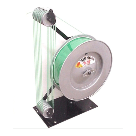
- Page 1 PSD-109 STRAP DISPENSER...
-
Page 2: General Safety Instructions
Do not load dispenser when you are in an awkward position. Use proper lifting techniques when loading a coil of strap into the dispenser. When mounting dispensers on wall and/or columns, use the proper Signode suspension brackets. 2. Tuck strap end back into dispenser straptroller area when not in use. -
Page 3: Table Of Contents
Operation Adjustments Parts Removal & Replacement Troubleshooting Parts List PSD-109 ACCUMULATING DISPENSER RIGHT-HAND PAYOFF (P/N 513684) LEFT-HAND PAYOFF (P/N 513685) INTRODUCTION This dispenser is to be used with power strapping equipment only. It is tension actuated and multi-roller design can accumulate 30 feet of retracted strap available at an actuation force of 5 pounds. -
Page 4: Major Components
MAJOR COMPONENTS RIGHT-HAND ORIENTATION LEFT HAND ORIENTATION... -
Page 5: Installation
INSTALLATION The dispenser should be placed at least 4 feet from the machinery that it will be serving.. The Options Section contains the optional hardware required to accommodate the less common locations relative to the machine. Once permanent location has been determined, use the base as a template to transfer the mounting hole locations to the floor to accept 3/8"... -
Page 6: Operation
COIL LOADING INSTRUCTIONS, Continued 8. Guide strap back up and over the next roller on the upper roller stack, (3). Repeat this process until all the rollers are loaded. The lead end of the strap should terminate at the innermost upper arm roller, (4). 9. -
Page 7: Adjustments
ADJUSTMENTS WEAR SAFETY GLASSES WITH SIDE SHIELDS WHICH CONFORM TO ANSI STANDARD Z87.1. FAILURE TO WEAR SAFETY GLASSES COULD RESULT IN SEVERE PERSONAL INJURY. PROTECT YOUR EYES. READ GENERAL SAFETY INSTRUCTIONS IN THE FRONT OF THIS MANUAL • Only trained people should service machine •... - Page 8 ADJUSTMENTS, Continued STRAP ACCUMULATION The amount of strap retracted from the strapping machine by the dispenser is dependent upon the position of the dancer arm when the brake is engaged. If the brake engages too near the lower end of the dancer arm travel, very little strap is retracted and accumulated.
-
Page 9: Parts Removal & Replacement
PARTS REMOVAL AND REPLACEMENT WEAR SAFETY GLASSES WITH SIDE SHIELDS WHICH CONFORM TO ANSI STANDARD Z87.1. FAILURE TO WEAR SAFETY GLASSES COULD RESULT IN SEVERE PERSONAL INJURY. PROTECT YOUR EYES. READ GENERAL SAFETY INSTRUCTIONS IN THE FRONT OF THIS MANUAL •... - Page 10 PARTS REMOVAL AND REPLACEMENT, Continued DANCER ARM COMPRESSION SPRING To remove and replace the dancer arm compression spring (6): 1. Place dancer arm in its lowest position. 2. Remove the pipe cap (1) from the spring housing (2). 3. Remove hex nut (3) and the spring stud (5). This may be difficult to do as thread sealant was applied during factory assembly.
- Page 11 ACTUATION CHAIN To remove and replace the actuation chain first remove the dispenser shaft (1): 1. Position the dancer arm at its lowest position. 2. Loosen the collars (2) on the dispenser shaft bearings (3). Remove the shaft assembly from the post and set it to the side.
- Page 12 PARTS REMOVAL AND REPLACEMENT, Continued 13. Tighten the hex nut until the stack is removed from the chain- then tighten no further. Chain slack can be detected as free rotational movement of the brake cam. If the dancer arm compression spring is overtightened, the chain or the connecting link may fail during operation.
-
Page 13: Troubleshooting
TROUBLESHOOTING The following items are the most common tool symptoms if problems should occur. For symptoms or remedies not shown, contact your Signode service representative for additional information and details. The following tool symptoms are shown in this manual: #1 SYMPTOM: Loose strap between roller stacks. - Page 14 TROUBLESHOOTING, Continued #5 SYMPTOM: Dispenser ‘Jerk’ starts. CAUSE REMEDY The dancer arm is traveling too high before Adjust the brake cam to release the brake the brake is released. sooner. See Adjustments Section. #6 SYMPTOM: Strap pulls out of machine. CAUSE REMEDY The dancer arm is traveling too high before...
- Page 15 BLANK...
-
Page 16: Parts List
PARTS LIST MAIN FRAME, LEVER ASSEMBLY AND DANCER ARM SPRING ASSEMBLY QTY. PART NO. DESCRIPTION 426364 Spring housing cap 426365 Spring housing liner 426366 Post 426368 Hex head cap screw, 5/16-24 x 3/4 426369 Lockwasher, 5/16 426371 Hex head cap screw, 3/8-16 x3 426372 Lockwasher, 3/8 426373... - Page 18 PARTS LIST, Continued UPPER ARM AND DANCER ARM ASSEMBLY QTY. PART NO. DESCRIPTION 426368 Hex head cap screw, 5/16-24 x 3/4 426369 Lockwasher, 5/16 423372 Lockwasher, 3/8 426373 Flat washer, 3/8 426396 Hex head cap screw, 3/8-16 x 8 426396 Hex head cap screw, 3/8-16 x 8 (Alternate) 517779 Keeper roller mounting plate...
- Page 20 PARTS LIST, Continued DISPENSER SHAFT ASSEMBLY QTY. PART NO. DESCRIPTION 426368 Hex head cap screw, 5/16-24 x 3/4 426369 Lockwasher, 5/16 426412 Flanged cartridge bearing, 1 dia. 426413 Bearing alignment plate 426423 Socket head machine screw, 10-24 x 5/8 426424 Lockwasher #10 426425 Dispenser flange...
- Page 22 PARTS LIST, Continued BRAKE CAMSHAFT ASSEMBLY QTY. PART NO. DESCRIPTION 426368 Hex head cap screw, 5/16-24 x 3/4 426369 Lockwasher, 5/16 426412 Flanged cartridge bearing, 1 dia. 426413 Bearing alignment plate 426415 Actuation chain 426418 Retaining ring, external, 1 426420 Sprocket key 426423 Socket head machine screw, 10-24 x 5/8...
- Page 24 ! ! ! ! ! ! ! ! SIGNODE 3620 WEST LAKE AVENUE GLENVIEW, ILLINOIS 60025 U.S.A. © Copyright 2009, Signode 512146 5/2009...
Need help?
Do you have a question about the PSD-109 and is the answer not in the manual?
Questions and answers