Advertisement
Quick Links
Advertisement

Related Manuals for Kitronik LINE FOLLOWING BUGGY V3


Summary of Contents for Kitronik LINE FOLLOWING BUGGY V3
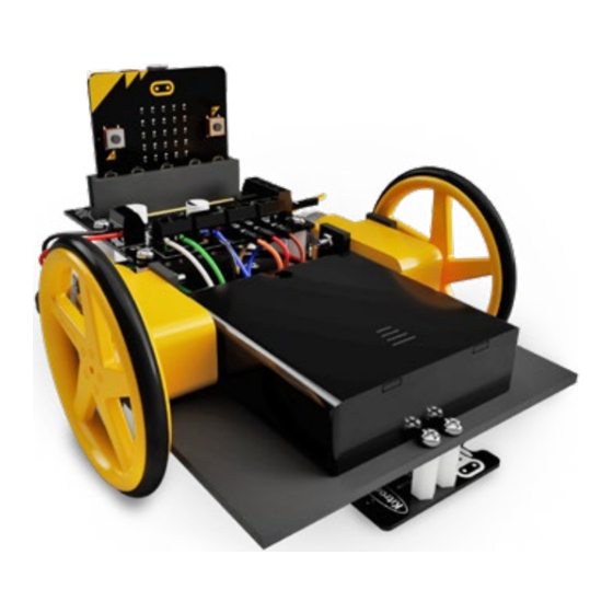
- Page 1 STAY ON TRACK WITH THE LINE FOLLOWING BUGGY V3 for BBC micro:bit V3.0...
-
Page 2: Build Instructions
BUILD INSTRUCTIONS LIST OF FIXINGS M3 NUTS & BOLTS SPACERS 20mm 30mm 12.7mm Using the four pieces of wire (white, green, blue and black) supplied with the chassis, strip and solder one end of each wire to each motor terminal (a small copper contact protruding from the end of the motor). This is done by putting the exposed wire through the hole on the contact and soldering into place. - Page 3 Remove the protective backing off the acrylic pieces. Take two of the ‘T’ shape acrylic pieces and push them through the two right hand slots in the base plate as shown below. Place Motor 1 (green and white wires) between the two pieces with the motor terminals pointing toward the rounded corners of the buggy and the axle pointing outwards.
- Page 4 To attach the caster to the buggy, align it as shown to the underside of the buggy and secure it using two M3 x 6mm screws and two M3 nuts. Attach the M3 x 20mm plastic spacers using four of the M3 x 6mm screws from underneath.
- Page 5 Attach the Motor Driver Board to the top of the plastic spacers using four more M3 x 6mm screws. Make sure the terminal blocks are facing the centre of the board.
- Page 6 Take the wires from the motors and connect them to the terminal blocks on the motor driver board in the following configuration: • Wire 1 on Motor 1 (White) goes into the ‘P12’ terminal. • Wire 2 on Motor 1 (Green) goes into the ‘P8’ terminal. •...
- Page 7 Using two M3 x 6mm screws, fix the two shorter spacers to the front of the buggy, on the underside as shown below. Mount the line following board to the spacers using two M3 x 6mm screws.
- Page 8 a) Split the jumper wires into a group of 4 (brown, red, orange & yellow). b) Using the wiring diagram below, slot the female ends of the wires onto the pins on the Line Following Board. NOTE: There are five pins available but only one of the ground pins (0V) is needed.
- Page 9 Using the sticky pad, attach the battery pack to the top of the buggy chassis with the switch poking through the rectangular cut-out. Attach the red and black wires in the terminal on the Motor Driver Board labelled ‘POWER’. Put the black wire in the left hand side of the terminal labelled ‘BLACK’...
- Page 10 TEST CODE Download the code here: kitronik.co.uk/5638 Now, let’s try the code out! Plug your BBC micro:bit into a USB port and it will show up as a storage device. Simply unzip, then drag and drop the .hex file you just downloaded onto the BBC micro:bit. The file might...
- Page 11 The small LED’s on the Line Following Board light up when the corresponding sensor passes over the line and can be used for visual feedback when developing and testing your own code. GET CODING! Visit kitronik.co.uk/5638 for help. See the online datasheet for a tuning guide.
- Page 12 UK by For more information on RoHs and CE please visit kitronik.co.uk/rohs-ce. Children assembling this product should be supervised by a competent adult. The product contains small parts so should be kept out of reach of children under 3 years old.
Need help?
Do you have a question about the LINE FOLLOWING BUGGY V3 and is the answer not in the manual?
Questions and answers