Advertisement
Quick Links
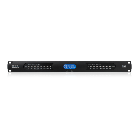
BB-1616DT
BlueBridge DSP
BlueBridge
Quick Start Guide
BlueBridge
TSD-BB44
ETHERNET
4 Channel Digital Signal Processor
BlueBridge
GREEN = SIGNAL
RED = PEAK
INPUT 1
INPUT 2
TSD-BB44
ETHERNET
4 Channel Digital Signal Processor
1601 Jack McKay Blvd. • Ennis, TX 75119 • 800.876.3333 • AtlasSound.com
GREEN = SIGNAL
RED = PEAK
INPUT 1
INPUT 2
1601 Jack McKay Blvd. • Ennis, TX 75119 • 800.876.3333 • AtlasSound.com
OUTPUT 4
EXTERNAL DC
G
–
POWER SUPPLY
OUTPUT 4
EXTERNAL DC
G
–
POWER SUPPLY
5V/12V/-12V
G
–
20W TOTAL
OUTPUT 2
5V/12V/-12V
G
–
20W TOTAL
OUTPUT 2
SCAN FOR TROUBLESHOOTING
SCAN FOR TROUBLESHOOTING
SERIAL NUMBER
SERIAL NUMBER
MAC ADDRESS
MAC ADDRESS
IP RESET
INPUT 3
IP RESET
INPUT 4
POWER
INPUT 3
INPUT 4
POWER
OUTPUT 3
INPUT 4
INPUT 3
+
G
–
+
G
–
+
G
–
+
OUTPUT 3
INPUT 4
INPUT 3
+
G
–
+
G
–
+
G
–
+
+
G
–
+
G
–
+
G
–
+
OUTPUT 1
INPUT 2
INPUT 1
+
G
–
+
G
–
+
G
–
+
OUTPUT 1
INPUT 2
INPUT 1
AtlasSound.com
1/16
Advertisement

Related Manuals for AtlasIED BlueBridge Series


Summary of Contents for AtlasIED BlueBridge Series
- Page 1 BlueBridge Quick Start Guide BB-1616DT BlueBridge DSP BlueBridge IP RESET TSD-BB44 ETHERNET 4 Channel Digital Signal Processor BlueBridge GREEN = SIGNAL RED = PEAK INPUT 1 INPUT 2 INPUT 3 IP RESET INPUT 4 POWER TSD-BB44 ETHERNET 4 Channel Digital Signal Processor 1601 Jack McKay Blvd.
- Page 2 The following is a Quick Start Guide to be used with the Atlas Sound BlueBridge processors. These models are part of the BlueBridge family of processors that are based on an open architecture platform that utilizes a drag and drop method for system designs. The intent for this Quick Start Guide is to give an overview on how to connect a BlueBridge device to a computer and access a DSP Hardware Block with the ability to pass audio through the Atlas processor.
- Page 3 BlueBridge Glossary of Terms BlueBridge Designer - The Software program used to create a Design Template to load into an Atlas BlueBridge DSP device. Blue Panel - A Software program used to identify DSP hardware devices on a network and navigate custom control pages created for the devices using the BlueBridge dsigner software.
- Page 4 BlueBridge Designer Software Glossary Term/Feature Location Identification Tags Online Mode Project View System Preset (AKA Live Mode) Atlas Processors (Hardware) Network View Control Devices System Blueprint Mode (AKA Functional Wiring Diagram) Project Design Elements Figure A Figure A shows the BlueBridge Designer main starting page. This is called System Blueprint Mode. Figure B shows the BlueBridge Designer Software with the TSD-BB44 DSP processor block opened.
- Page 5 Turning The Unit On Figure 1 Figure 2 After connecting the power supply, the front panel input LEDs will illuminate red for approximately 60 - 120 seconds as shown in Figure 1. The interior relays will audibly click and then the input LEDs will turn Off. The power and ethernet LEDs will remain illuminated as shown in Figure 2. The TSD-BB22 and TSD-BB44 are factory pre-loaded with a file that connects Input 1 to Output 1, Input 2 to Output 2, etc.
- Page 6 Figure 5 Open Unity Design Test File for Model Being Installed Choose the Unity Test file for the unit being installed and select “Open” as shown in Figure 5. This design file will provide basic information for loading a design file onto the device. The Unity Test file will open in the BlueBridge Designer application as illustrated in Figure 6.
- Page 7 Connecting The Device to the Network • Connect a Windows computer to the network (wired or wireless). ® • Connect the device to the network using a standard Cat5e ethernet cable. • Ensure that DHCP is enabled in your computer’s network settings. •...
- Page 8 Not Detected Detected & Connected Figure 9 • Note: If you have used this software with any Atlas BlueBridge hardware devices that were previously connected, you may still see them appear in the Network view as shown in Figure 9. These can be identified by the model number. The RED dot in the upper left corner of the device window indicates the device is no longer detected.
- Page 9 • Click on the “Project View” button as shown in Figure 10. This will take you back to the Blue Print Mode window view. The detected unit will now appear in the main window as shown in Figure 11. Unmapped DSP Unit Will Appear Right Click On Hardware Device To Map the Device...
- Page 10 Configuring the Unit Online Note: When in Online Mode, the BlueBridge Hardware Device and the Design File are communicating and all adjustments are live and in real time. Click To Switch From System Blueprint Mode To Online Mode Figure 16 •...
- Page 11 • The Design file will now upload the file into the Processor hardware as shown in Figure 19. The wait time will depend on the size of the design file and can take several minutes to finish. Figure 19 • The TSD Processor is now Online (Live) and ready to be controlled.
- Page 12 • Once the DSP Hardware Device is open, the design file can be accessed as shown in Figure 21. The example below shows a TSD-BB44 Unity Design Test file factory pre-loaded where as the input block is wired to the output block. Note: Further on, there will examples of designs with DSP Modules applied to the Design file.
- Page 13 • Clicking the Mic/Line Pre-Amp Setup will launch a second window as shown in Figure 23. • In this window you select Mic or Line Level, Phantom Power and fine tune Analog Mic/Line trim level as seen in Figure 23. Analog Mic Pre Adjust Figure 23 •...
- Page 14 • After any adjustments are made, the project file should be saved as shown in Figure 25. Save Project Figure 25 After the device has been connected to the network and mapped to a design file, make sure to save the file. You are now ready to start a new project. When comparing BlueBridge to other DSP software, you will see that it is user friendly.
- Page 15 Design Example The design shown in Figure 28 illustrates a DSP based design for a small hotel conference/meeting room set up. It is based on the Atlas TSD-BB44, Atlas TSD-PA122G amplification and Atlas FAP42T speaker systems. There is a Mic Input located in each of the four rooms and the rooms can be opened up to each other to make bigger meeting spaces.
- Page 16 Selecting a processing Block inside the design, and clicking it open, is fast and intuitive when needing to make fine adjustments to the system. Figure 30 and Figure 31 are examples of the Compressor and Parametric Equalizer Processing Blocks opened in this systems design. Figure 30 Figure 31 The Blue Panel Control Page can be setup in almost unlimited configurations and with multiple pages.
Need help?
Do you have a question about the BlueBridge Series and is the answer not in the manual?
Questions and answers