Table of Contents
Advertisement
Quick Links
Advertisement
Table of Contents

Related Manuals for FlyTech K959

Summary of Contents for FlyTech K959
- Page 1 USER MANUAL VERSION 1.0 October 2020 Panel PC Hardware System...
- Page 2 Copyright 2020 All Rights Reserved Manual Version 1.0 The information contained in this document is subject to change without notice. We make no warranty of any kind with regard to this material, including, but not limited to, the implied warranties of merchantability and fitness for a particular purpose. We shall not be liable for errors contained herein or for incidental or consequential damages in connection with the furnishing, performance, or use of this material.
- Page 3 13. The medical PC can be cleaned in accordance with normal clinical cleaning practices, including wiping with water or medical grade wipes, provided no substance containing acids or cleaning alkali liquids is used. 14. Medical grade wipes must not contain more than 80% alcohol content measured against the total content of the wipe.
- Page 4 CE MARK This device complies with the requirements of the EEC directive 2014/30/EU with This device complies with part 15 of the FCC rules. Operation is subject to the following two conditions: (1) This device may not cause harmful interference. (2) This device must accept any interference received, including interference that may cause undesired operation.
- Page 5 Avertissement Batterie Risque d’explosion si la batterie est remplacée par un élément incompatible. Jetez les batteries usagées selon les instructions des dispositions locales . Avertissement de sécurité Remarque: Pour répondre à la norme IEC60950-1 alinéa 2.5 (sources d’énergie limitées, LPS) liés la législation, les périphériques doivent être conforme 4.7.3.2 “Matériaux pour enceinte coupe-feu»...
- Page 6 Troubleshooting For your own safety and that of your equipment, always take the following precautions. Disconnect the power plug (by pulling the plug, not the cord), from your computer if any of the following conditions exists: • The power cord or plug becomes frayed or otherwise damaged. •...
- Page 7 Revision History Changes to the original user manual are listed below: Revision Description Date • Initial release October, 2020...
-
Page 8: Table Of Contents
Table of Contents 1. Intended Use ......... 1 2. Packing List ........2 2-1. Standard Items ..............2 3. System View ........3 3-1. Front & Side View ............3 3-2. Rear & Bottom View ............4 3-3. I/O View ................4 3-4. Dimension ................5 4. - Page 9 ........ 13 ....... 15 7-1. D87U Motherboard Layout ..........15 7-2. Connectors & Functions ..........16 7-3. Jumper Setting ...............17...
-
Page 10: Intended Use
Intended Use The Medical Computer is a computing device capable of storing, retrieving and sending data electronically. This Medical Computer, including its user interface, RTC battery, PCB and power supply, is intended to be fixed to a VESA wall mount in medical care environment. This Medical Computer Hardware System must be operated by professional personnel (i.e., doctor, nurse...). -
Page 11: Packing List
Packing List 2-1. Standard Items a. System b. Power adapter c. Power cord d. Battery Note: Power cord will be supplied differently according to various region or country. -
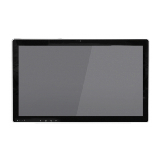
Page 12: System View
System View 3-1. Front & Side View Item No. Description batteries status capacitive sensor touch function keys (from left to right: Volume down /Volume up /Brightness darker / Brightness lighter) Power button... -
Page 13: Rear & Bottom View
3-2. Rear & Bottom View Item No. Description 100 x 100 VESA mounting holes 75 x 75 VESA mounting holes Battery door Cable cover 3-3. I/O View a b c Item No. Description USB 1.1/ USB 1.0 USB 3.0 HDMI DC in USB 1.1 (x2) -
Page 14: Dimension
3-4. Dimension 533.13mm 59mm... -
Page 15: Basic Operation
Basic Operation 4-1. Powering On & Off To activate the system, push 2-3 seconds and release the power button, the display will come on in a few seconds. NOTE: The system must be plugged into power adapter or battery charged before turning on for the first time. To turn off the system, power off the device safely using software function that... -
Page 16: Charging The Battery
4-2. Charging the Battery 1. The system is equipped with 2 hot- swappable batteries. The batteries may be charged by connecting the supplied power adapter directly to the DC-in port on the system. 2. The system will charge in the order of battery 1 to battery 2. -
Page 17: Battery Level Indication
4-3. Battery Level Indication Each battery provides an battery level indicator LED on the front of the system. The signals charge status are as follows: Battery full charged GREEN Battery charging GREEN blilnk slowly Battery Battery standby GREEN Battery error blink quickly DC in Mode Without battery... -
Page 18: Battery Discharging Mode Flowchart
4-4. Battery Discharging Mode Flowchart Battery discharging will be started from Battery 1 when system boot on battery discharging mode. Battery 2 Battery 1 When Battery 1 lock been released Battery 2 Battery 2 Battery 2 slot capacitive is capacitive is is empty higher than 6% lower than 6%... -
Page 19: System Assembly
System Assembly 5-1. Removing the Cable Cover 1. Place the system face down, make sure not to scrath the screen. 2. Press and pull the cable cover outwards to release it from the system. 5-2. Replacing the Battery 1. Place the system face down, make sure not to scrath the screen. -
Page 20: Removing The Rear Cover
5-3. Removing the Rear Cover 1. To open the rear cover of the system, please follow the steps described in Chapter 5-1 and 5-2 to remove the cable cover and batteries first. 2. Remove the rubber pads (x9) and loosen the screws (x10) of the rear cover. -
Page 21: Replacing The Ssd
Installing a RAM moudle Slide the memory module into the memory slot anvd press down until the ejector clips snaps in place. 3. Find the RAM module and flip the ejector clips outwards to remove the memory module from the memory slot. 5-5. - Page 22 Model Name K959 w/isolation Mainboard D87U Intel SKYLAKE U CPU i5-6300U 2.4GHz, LLC 3M System memory DDR4 2133 MHz (32GB Max) ; 2 Channel LCD/Touch Panel LCD size 21.5" LED LCD Brightness 250 nits Maximal resolution 1920 x 1080 Touch screen type...
- Page 23 *Recommended length of screw (L): Thickness (VESA mount) + 5mm OS support Windows IOT 10 (64-bit) Manufactory information: Factory: Flytech Technology Co., Ltd. Address: NO.36 Huaya 3 Rd., Guishan Township, Taoyuan County 33383, Taiwan Tel No: 886-3-272-9688 Fax No: 886-3-272-9666 Adaptor Manufacturer: MEAN WELL ENTERPRISES CO., LTD.
- Page 24 7-1. D87U Motherboard Layout CN16 CN11 CN28 CN27 MINI-PCIE1 SKT2 CN22 CN21 CN14 CN23 DIMM_A1 DIMM_B1 CN15 SKT1 CN17 CN19 CN13 CN18 CN12 CN26 CN20 CN25 CN10 FAN1 PCIE1 BAT1...
- Page 25 7-2. Connectors & Functions Connector Function CN1/2 SATA power connector EC debug port Printer connector M.2 WiFi socket SDV connector CN8/9/10 USB2.0 connector CN11 COM4 connector CN12 Inverter connector CN13 eDP connector CN14 Bedside connector CN15 DP/HDMI Connector CN16 DICOM Connector CN17 DICOM for LVDS_VDD_EN CN18...
- Page 26 7-3. Jumper Setting Isolator USB (up port) speed select Function USB1.0 Isolator USB (down port) speed select Function USB1.1 Audio Mono select Function Mono LCD ID Setting LVDS Resolution Output Interface Bits Channel 1920 x 1080 Dual LVDS Panel Jumper open...
- Page 27 Isolation Board Layout USB1 COM1 Isolator USB (up port) speed select ( on isolation board ) Function USB1.0 Isolator USB (down port) speed select ( on isolation board ) Function USB1.0 • USB1.1 • USB2.0 (reduction of speed) • USB3.0 (reduction of speed)) The USB setting for Keyboard: USB1.0 Keyboard ->...