
Subscribe to Our Youtube Channel
Related Manuals for Dometic CT 3050


Summary of Contents for Dometic CT 3050
- Page 1 Installation Instructions Cassette Toilet for Recreation Vehicles CT 3050 CTS 3050 CTW 3050 CTLP 3050 CT 3110 CTS 3110 CTW 3110 CTLP 3110 INSTALLATION INSTRUCTIONS CASSETTE TOILET T.B. MBA 01/2008 N 1-1 242 6011-64en English...
- Page 2 Dometic GmbH In der Steinwiese 16 D-57074 Siegen www.dometic.com © Dometic GmbH - 2007 - Subject to change without prior notice - Printed in Germany...
-
Page 3: Table Of Contents
Table of contents General ..........Guide to these operating instructions . -
Page 4: General
No part of useful guidance. these instructions may be reproduced, copied or utilised in any other way without written aut- horisation by Dometic GmbH, Siegen. Environmental tip Explanation of symbols used in this manual Environmental tip gives you useful guidance for saving energy and disposal of the appliance. -
Page 5: Limitation Of Liability
Use of sanitary additives and regulations as well as the current state of Um die stoffliche Verwertung der recyclingfä- the art. Dometic reserves the right to make higen Verpackungsmaterialien sicherzustellen, changes at any time which are deemed to be sind diese den ortsüblichen Sammelsystemen in the interest of improving the product and zuzuführen. -
Page 6: Safety Instructions
Safety instructions 2.0 Safety instructions Intended use This toilet is designed for installation in recrea- tion vehicles such as caravans or motorhomes. Installation notes The toilet must be in principle installed so that it is accessible for maintenance work, can be easily installed and dismantled and removed from the vehicle without great effort. -
Page 7: Description Of Model
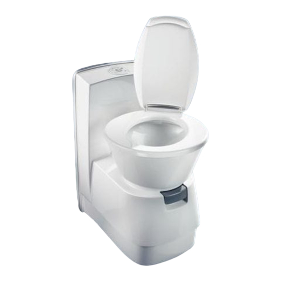
Description of model 3.0 Description of model Model identification Explanation of components Example : 3 x x x Model range (LP) free-standing without flush water tank,with console free-standing with integrated flush water tank LP = Low Profile, low con- sole Cassette Toilet Fig. -
Page 8: Installation Of Toilet
The description for the installation of the service CAUTION! door can be found in the document supplied All components of the system must be instal- (Dometic Seitz SK 5) (optional/depending on led in frost-protected areas. In minus tempe- model). ratures there is a risk of damage due to frost. -
Page 9: Installing The Ct 3Xxx Toilet
Installing the toilet 4.3.1 Installing the CT 3xxx toilet 4.3.1.1 Fitting the CT 3xxx toilet Once the toilet is installed in the desired posi- The free-standing CT 3xxx model has no inte- tion, bolt down the floor plate with the four grated water tank. -
Page 10: Installing The Control And Operator Panel Of The Ct 3Xxx Toilet
Installing the toilet Connect the electric cables on the couplers to 4.3.1.2 Installing the control and operator install the control and operator panel (are sup- panel of the CT 3xxx toilet plied separately). Install the control and operator panel for the CT 3xxx toilet in an easily accessible position on the wall. -
Page 11: Installing The Cts 3Xxx, Ctw 3Xxx And Ctlp 3Xxx Toilets
Installing the toilet 4.3.2.1 Fitting the wall holder 4.3.2 Installing the CTS 3xxx, CTW 3xxx and CTLP 3xxx toilets Fit the wall holder (Fig. 16) in the designated position (see table, Fig 18). The CTW 3xxx model has an integrated water tank, while the CTS 3xxx model does not. -
Page 12: Fitting The Cts 3Xxx, Ctw 3Xxx And Ctlp 3Xxx Toilets
Installing the toilet 4.3.2.2 Fitting the CTS 3xxx, CTW 3xxx and CTLP 3xxx toilets Place the entire toilet module in the desired position in front of the wall holder. Lift the toi- let. Then place the toilet so that the part on the side of the wall of the housing hooks into the the wall holder (Fig. -
Page 13: Water Connection
Installing the toilet Water connection CAUTION! The water supply is connected via a module If the water connection module is installed (Fig. 10) where the water feed hose is atta- below the water level, there is a risk of foul ched. -
Page 14: Ventilation
Installing the toilet Ventilation Open the duct (a) for the ventilation hose in the top area of the door frame (press out spraying varnish on the outside, drill through on the inside). Außenseite Innenseite Fig. 24 Place the ventilation hose on the integrated ventilation aperture of the service door as illu- strated. -
Page 15: Electric Connection
Installing the toilet Electric connection CAUTION! Electric connection must be carried out by trained staff. 4.6.1 System diagrams 4.6.1.1 System diagram (CTW 3xxx model with integrated water pump) 12V DC Control and operator panel Fig. 26 Supply voltage: : 12 V DC 12V connection cable profile : min. -
Page 16: Ct/ Cts/ Ctw 3Xxx System Diagrams
Installing the toilet 4.6.1.2 System diagrams (CT/CTS/CTLP 3xxx models with external water pump) 12V DC pump Control and operator panel Fig. 27 Supply voltage: : 12 V DC 12V connection cable profile : min. 1.5 mm² Toilet control fuse : 7.5 A (integrated automobile fuse) Current consumption of the pump : max. -
Page 17: Circuit Diagrams
Installing the toilet 4.6.2 Circuit diagrams 4.6.2.1 Circuit diagram (models with internal water tank, model CTW 3xxx) Fig. 28... -
Page 18: Circuit Diagram (Models With Internal Water Tank)
Installing the toilet 4.6.2.2 Circuit diagram (models with external water tank Fig. 29... - Page 19 Installing the toilet...
-
Page 20: Annex
Installing the toilet Annex 4.7.1 Dimensioned sketches 4.7.1.1 CT 3xxx... -
Page 21: Ctlp 3Xxx
Installing the toilet 4.7.1.2 CTLP 3xxx... - Page 22 Installing the toilet 4.7.1.3 CTS / CTW 3xxx...
-
Page 23: Templates
Installing the toilet 4.7.2 Templates 4.7.2.1 Template 1 for control and operator panel installation...
Need help?
Do you have a question about the CT 3050 and is the answer not in the manual?
Questions and answers