Dometic CT4110 Installation Manual
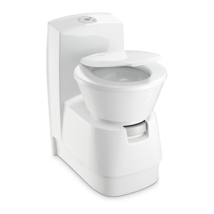
Cassette toilet for recreational vehicles
Hide thumbs
Also See for CT4110:
- Operating manual (84 pages) ,
- Installation manual (60 pages) ,
- Operating instructions manual (74 pages)
Table of Contents
Advertisement
Quick Links
Cassette toilet for recreational
EN
vehicles
Installation manual . . . . . . . . . . . . . . . 2
Toilettes à cassette pour
FR
véhicules de loisirs
Notice de montage . . . . . . . . . . . . . . 20
Inodoros de cassette para
ES
vehículos de tiempo libre
Instrucciones de montaje . . . . . . . . . 40
Sanitário de cassete para
PT
veículos de recreio
Instruções de montagem . . . . . . . . . 60
CT4110, CTS4110
"More information https://www.caravansplus.com.au"
Advertisement
Table of Contents

Related Manuals for Dometic CT4110


Summary of Contents for Dometic CT4110
- Page 1 Instrucciones de montaje ..40 Sanitário de cassete para veículos de recreio Instruções de montagem ..60 CT4110, CTS4110 “More information https://www.caravansplus.com.au"...
- Page 2 Dometic Group is a customer-driven, world-leading provider of leisure products for the RV, automotive, truck and marine mar- kets. We supply the industry and aftermarket with a complete range of air conditioners, refrigerators, awnings, cookers, sanita- tion systems, lighting, mobile power equipment, comfort and safety solutions, windows, doors and other equipment that make life more comfortable away from home.
-
Page 3: Table Of Contents
Table of contents 1.0 General ..........4 Guide to these installation instructions . -
Page 4: General
No part of useful guidance. these instructions may be reproduced, copied or utilised in any other way without written aut- horisation by Dometic GmbH, Siegen. Environmental tip Explanation of symbols used in this manual Environmental tip gives you useful guidance for saving energy and disposal of the appliance. -
Page 5: Limitation Of Liability
Dometic reserves the right to make changes at any time which are deemed to be in the interest of improving the product and safety. -
Page 6: Description Of Model
Description of model Description of model Technical data Model identification Supply voltage: 12 V DC Example: Current consumption: max. 5 A with external CT S 4110 pump. Dimensions: s. details on page 15 Operating temperature: 0 °C up to +50 °C (32 °F up to +122 °F) S = free-standing, without flush water tank, with console Required pump output: minimum 7 l/min... -
Page 7: Explanation Of Components
Installing the toilet components Installing the service door The description for the installation of the ser- vice door can be found in the document sup- plied Dometic Seitz SK4, SK5 (optional/ depending on model). Create wall apertures 4.2.1 Wall aperture service door... -
Page 8: Installing The Toilet
Installing the toilet Installing the toilet NOTICE! All components of the system must be installed in frost-protected areas. In minus temperatures there is a risk of damage due to frost. Allow sufficient space so as not to limit the operation of the emptying valve. Fig. -
Page 9: Installing The Control And Operator Panel Of The Ct 4110 Toilet
Installing the toilet Then attach the toilet housing (with no more inch than 7 screws, not enclosed) to the wall (Fig. 10, 11). 2.36 Fig. 13 In order to insert the control panel in the wall aperture, press the holding springs (1) of the control and operator panel back. -
Page 10: Placing The Cts 4110 Toilet
Installing the toilet 4.3.2.1 Fitting the wall holder 4.3.2 Placing the CTS 4110 toilet Fit the wall holder (Fig. 19) in the designated The CTS 4110 model has no integrated water position (see table, Fig. 20, 21) tank. The control and operator panel is integrated in the housing with this model. -
Page 11: Fitting The Cts 4110 Toilet
Installing the toilet 4.3.2.2 Fitting the CTS 4110 toilet Place the entire toilet module in the desired position in front of the wall holder. Lift the toi- let. Then place the toilet so that the part on the side of the wall of the housing hooks into the the wall holder (Fig. -
Page 12: Water Connection
Installing the toilet Place the ventilation hose on the integrated Water connection ventilation aperture of the service door as illu- The water supply is connected via an eletric strated. solenoid valve (1), which is fitted in the toilet housing. Fit the fresh water supply pipe to the water inlet (2) with a 1/2 ″... -
Page 13: Electric Connection
Installing the toilet Electric connection Note the following instructions before installa- tion of the cassette toilet: 4.6.1 System diagrams Connect the toilet to a suitable power supply via the main connection block of 4.6.1.1 General system diagram the vehicle (Fig. 31). The toilet must not be directly connected in parallel to other electrical circuits, CAUTION! -
Page 14: System Diagrams (Cts 4110 Models With External Water Pump)
Installing the toilet 4.6.1.2 System diagrams (CTS 4110 models with external water pump) Supply voltage: 12 V DC 12V connection cable profile : min. 1.5 mm² Toilet control fuse : 7.5 A 12V DC (integrated automobile fuse) Current consumption of the pump : max. 5A NOTICE! Pump The external water pump must not exceed... -
Page 15: Dimensioned Sketches
Installing the toilet Dimensioned sketches 4.8.1 CT 4110 Dimensions in mm “More information https://www.caravansplus.com.au"... - Page 16 Installing the toilet Dimensions in inch “More information https://www.caravansplus.com.au"...
-
Page 17: Cts 4110
Installing the toilet 4.8.2 CTS 4110 Dimensions in mm “More information https://www.caravansplus.com.au"... - Page 18 Installing the toilet Dimensions in inch “More information https://www.caravansplus.com.au"...
-
Page 19: Template For Control And Operator Panel Installation
Installing the toilet Template for control and operator panel installation Original size “More information https://www.caravansplus.com.au"...
Need help?
Do you have a question about the CT4110 and is the answer not in the manual?
Questions and answers