Dometic CT 4050 Installation Instructions Manual
Cassette toilet for recreation vehicles
Hide thumbs
Also See for CT 4050:
- Operating manual (324 pages) ,
- Installation manual (252 pages) ,
- Operating instructions manual (74 pages)

Related Manuals for Dometic CT 4050


Summary of Contents for Dometic CT 4050
- Page 1 Installation Instructions Cassette Toilet for Recreation Vehicles CT 4050 CTS 4050 CTW 4050 CTLP 4050 CT 4110 CTS 4110 CTW 4110 CTLP 4110 CTP 4110 N 1-1 MBA 01/2012 “More information https://www.caravansplus.com.au"...
- Page 2 CT 4050 CT 4110 CTLP 4050 CTLP 4110 CTS 4050 CTS 4110 CTW 4050 CTW 4110 Dometic GmbH In der Steinwiese 16 D-57074 Siegen www.dometic.com © Dometic GmbH - 2011 - Subject to change without prior notice “More information https://www.caravansplus.com.au"...
-
Page 3: Table Of Contents
Table of contents General ..........20 Guide to these operating instructions . -
Page 4: General
No part of useful guidance. these instructions may be reproduced, copied or utilised in any other way without written aut- horisation by Dometic GmbH, Siegen. Environmental tip Explanation of symbols used in this manual Environmental tip gives you useful guidance for saving energy and disposal of the appliance. -
Page 5: Limitation Of Liability
In order to ensure that the recyclable packa- the art. Dometic reserves the right to make ging materials are re-used, they should be changes at any time which are deemed to be sent to the customary local collection system. -
Page 6: Safety Instructions
Safety instructions 2.0 Safety instructions Intended use This toilet is designed for installation in recrea- tion vehicles such as caravans or motorho- mes. Installation notes The toilet must be in principle installed so that it is accessible for maintenance work, can be easily installed and dismantled and removed from the vehicle without great effort. -
Page 7: Description Of Model
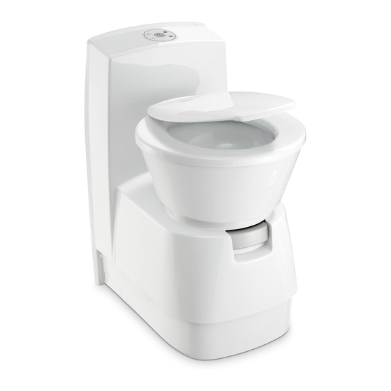
Description of model 3.0 Description of model Explanation of components Model identification Example : 4050 4110 for installation in wet cell (LP) free-standing without flush water tank,with console W = free-standing with integrated flush water tank LP = Low Profile, low con- sole Cassette Toilet Fig. -
Page 8: Installation Of Toilet
Use the vice door can be found in the document sup- template (1) , Item 5.3.1., to make the apertu- plied Dometic Seitz SK4, re for the flap. You can find the installation (optional/depending on model). -
Page 9: Installing The Ct 4Xxx Toilet
Installing the toilet 4.3.1 Installing the CT 4xxx toilet 4.3.1.1 Fitting the CT 4xxx toilet Once the toilet is installed in the desired posi- The free-standing CT 4xxx model has no inte- tion, bolt down the floor plate with the six grated water tank. -
Page 10: Installing The Control And Operator Panel Of The Ct 4Xxx Toilet
Installing the toilet To allow better cleaning of the cassette hou- In order to insert the control panel in the wall aperture, press the holding springs (1) of the sing the base plate is additional equipped with two covers (1) for the fixing screws (models control and operator panel back. -
Page 11: Installing The Cts 4Xxx, Ctw 4Xxx And Ctlp 4Xxx Toilets
Installing the toilet 4.3.2 Installing the CTS 4xxx, 4.3.2.1 Fitting the wall holder CTW 4xxx and CTLP 4xxx toilets Fit the wall holder (Fig. 18) in the designated position (see table, Fig 20). The CTW 4xxx model has an integrated water tank, while the CTS 4xxx model does not. -
Page 12: Fitting The Cts 4Xxx, Ctw 4Xxx And Ctlp 4Xxx Toilets
Installing the toilet 4.3.2.2 Fitting the CTS 4xxx, CTW 4xxx and CTLP 4xxx toilets Place the entire toilet module in the desired position in front of the wall holder. Lift the toi- let. Then place the toilet so that the part on the side of the wall of the housing hooks into the the wall holder (Fig. -
Page 13: Water Connection
Einbau der Toilette Water connection Flap installation Apply the flap when using CTW 4xxx models The water supply is connected via a magnet valve (1), which is fitted in the toilet housing. with an integrated water tank. To install the Fit the fresh water supply pipe to the connec- flap, use the template (1), Item 5.3.1, in order tion nozzle (2) with a spring clamp. -
Page 14: Ventilation
Installing the toilet Ventilation 4.6.2 Ventilation with SK 4 Create an aperture in the recess floor (diame- 4.6.1 Ventilation with SK 5 ter approx. 12 mm). Insert the ventilation hose Open the duct (a) for the ventilation hose in the into this aperture for extraction to the outside. -
Page 15: Electric Connection
Installing the toilet Electric connection Note the following instructions before installa- tion of the cassette toilet: 4.7.1 System diagrams Connect the toilet to a suitable power supply via the main connection block of 4.7.1.1 General system diagram the vehicle (Fig. 30). The toilet must not be directly connected in parallel to other consumers, otherwise CAUTION! -
Page 16: System Diagram Ctw 4Xxx
Installing the toilet 4.7.1.2 System diagram (CTW 4xxx model with integrated water pump) Supply voltage: 12 V DC 12V connection cable profile : : 12V DC min. 0.75 mm² Toilet control fuse : 7.5 A (integrated automobile fuse) Current consumption of the pump : max. 2 A Control and operator panel Fig. -
Page 17: Circuit Diagram (Models With Internal Water Tank, Model Ctw 4Xxx)
Anhang/Annex/Bilaga Schaltschemata / Circuit diagrams / Schémas de circuit / Kopplingsscheman 5.1.1 Schaltschema (interner Wassertank im Tankgehäuse, Modell CTW 4xxx) Circuit diagram (models with internal water tank, model CTW 4xxx) Schéma de circuit (modèles avec réservoir d'eau interne, modèle CTW 4xxx) Kopplingsschema (modell CTW 4xxx med integrerad vattentank) Fig. -
Page 18: Circuit Diagram (Models With Internal Water Tank And Sog Ventilation)
Anhang/Annex/Bilaga 5.1.2 Schaltschema (interner Wassertank und SOG-Ventilation) Circuit diagram (models with internal water tank and SOG ventilation) Schéma de circuit (modèles avec réservoir d'eau interne et ventilation SOG) Kopplingsschema (modeller med integrerad vattentank och SOG ventilation) Fig. 35 “More information https://www.caravansplus.com.au"... -
Page 19: Circuit Diagram (Models With External Water Tank)
Anhang/Annex/Bilaga 5.1.3 Schaltschema (Modelle mit externem Wassertank) Circuit diagram (models with external water tank) Schéma de circuit (modèles avec réservoir d'eau externe) Kopplingsschema (modeller med extern vattentank) 6-poliger Stecker 6 point plug Fig. 36 4-poliger Stecker 4 point plug Fig. 37 “More information https://www.caravansplus.com.au"... -
Page 20: Circuit Diagram (Models With External Water Tank And Sog Ventilation)
Anhang/Annex/Bilaga 5.1.4 Schaltschema (Modelle mit externem Wassertank und SOG-Ventilaton) Circuit diagram (models with external water tank and SOG ventilation) Schéma de circuit (modèles avec réservoir d'eau externe et venitlation SOG) Kopplingsschema (modeller med extern vattentank och SOG ventilation) 6-poliger Stecker 6 point plug Fig. - Page 21 Anhang/Annex/Bilaga 5.1.5 Schaltschema (externer Wassertank) NUR FÜR AUSTRALIEN Circuit diagram (external water tank) FOR AUSTRALIA ONLY Schéma de circuit (réservoir d'eau externe) SEULEMENT POUR L’ AUSTRALIE Kopplingsschema (modeller med extern vattentank) ENDAST FÖR AUSTRALIEN Fig. 40 “More information https://www.caravansplus.com.au"...
-
Page 22: Circuit Diagram (External Water Tank And Sog Ventilation) Australia
Anhang/Annex/Bilaga 5.1.6 Schaltschema (externer Wassertank und SOG-Ventilation) AUSTRALIEN Circuit diagram (external water tank and SOG ventilation) AUSTRALIA Schéma de circuit (réservoir d'eau externe et ventilation SOG) AUSTRALIE Kopplingsschema (extern vattentank och SOG ventilation) AUSTRALIEN Fig. 34 “More information https://www.caravansplus.com.au"... -
Page 23: Legend
Anhang/Annex/Bilaga 5.1.7 Légende / Förklaring Français Svenska Reedswitch tank status / Reedswitch tank status / Commutateur Reed " Etat réservoir " Reed-brytare "Tankstatus" (floater) Reedswitch flush tank / (floater) Reedswitch flush tank / Flotteur " Indicateur d'eau fraîche " Flottör "Färskvattendisplay" Micro switch position of cassette / Micro switch position of cassette / Micro-commutateur "... - Page 24 Anhang/Annex/Bilaga Maßskizzen / Dimensioned sketches / Croquis cotés/ Måttskisser 5.2.1 CT 4xxx “More information https://www.caravansplus.com.au"...
- Page 25 Anhang/Annex/Bilaga 5.2.2 CTLP 4xxx “More information https://www.caravansplus.com.au"...
- Page 26 Anhang/Annex/Bilaga 5.2.3 CTS 4xxx “More information https://www.caravansplus.com.au"...
- Page 27 Anhang/Annex/Bilaga 5.2.4 CTW 4xxx “More information https://www.caravansplus.com.au"...
- Page 28 Anhang/Annex/Bilaga Schablonen / Templates / Gabarits / Schabloner 5.3.1 Schablone für Tankklappe (1) und Servicetüre (2) , (3) 5.3.1 Template for flap (1) and service door (2) , (3) 5.3.1 Gabarits pour le clapet de réservoir (1) et de la porte de service (2) , (3) 5.3.1 Schablon för montering tanklucka (1) och servicedörrar (2) , (3) An Außenseite des Fahrzeugs anlegen ! Fit to the outside of the vehicle !
- Page 29 Anhang/Annex/Bilaga 5.3.2 Schablone (4) für Einbau Kontroll- und Bedienfeld 5.3.2 Template 4 for control and operator panel installation 5.3.2 Gabarit (4) pour le montage du panneau de commande et contrôle 5.3.2 Schablon 4 för installation av kontroll- och manöverpanelen Originalgröße Originalgröße Original size Original size...
Need help?
Do you have a question about the CT 4050 and is the answer not in the manual?
Questions and answers
How do I get the water out of the flushing tank when the flush doesn’t work?
To remove water from the flushing tank of a Dometic CT 4050 when the flush is not working, follow these steps:
1. Drain the freshwater tank completely.
2. Drain the water supply system fully.
3. Operate the flush button until no more water is in the pipes (if possible).
4. If the flush button does not work, manually disconnect or drain the water line connected to the flush system.
5. Ensure the cassette tank is emptied and rinsed.
6. Let the drain pipe remain open to allow the tank to dry.
These steps help prevent damage and remove remaining water even if the flush is not functioning.
This answer is automatically generated