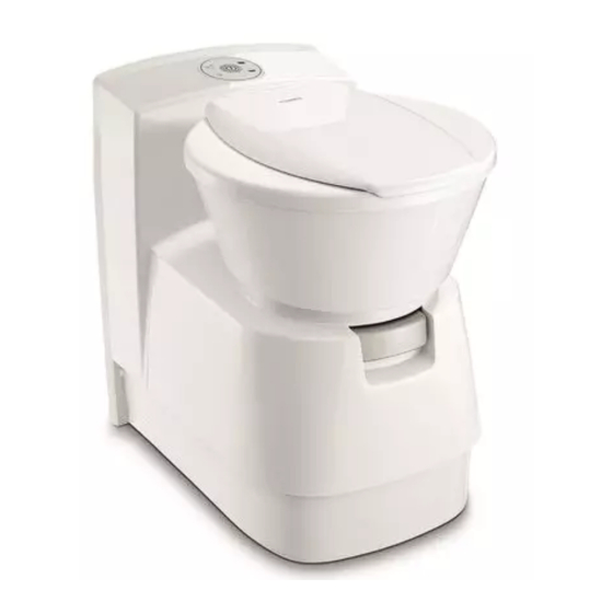
Do you have a question about the CTLP4110 and is the answer not in the manual?
Questions and answers
Rodney Gatt
March 7, 2025
Hi , My Dometic ctelp 4110 switch was not working so I replaced it with a new Dometic ctlp 4110 switch but the new switch is not working. I have power to the input and a red light is on at the top left side of the new switch, but it does not operate, any suggestion please ?
1 comments:
Mr. Anderson
May 14, 2025
If the Dometic CTLP4110 switch has power and shows a red light but is not operating, possible issues include:
- Faulty electronics - Faulty pump - Faulty magnetic valve - Dirty screen on the magnetic valve
These components may need to be checked and replaced if necessary.
CT4000 Please read this instruction manual carefully before installation and first use, and store it in a safe place. If you pass on the product to another person, hand over this instruction manual along with it. Table of contents Explanation of symbols ........4 Safety instructions .
Explanation of symbols CT4000 Explanation of symbols CAUTION! Safety instruction: Failure to observe this instruction can lead to injury. NOTICE! Failure to observe this instruction can cause material damage and impair the function of the product. NOTE Supplementary information for operating the product. Safety instructions The manufacturer accepts no liability for damage in the following cases: •...
The following model versions of the toilet are available: • CT4050: detached, without water tank, without console • CTLP4110: detached, without water tank, low console • CTS4110: detached, without water tank, with console The 4050 models can be installed in a wet room.
Technical description CT4000 Description of the components No. in fig. 1 Designation Housing for cassette tank Draining slider for toilet bowl Toilet bowl, ceramic Lid and seat, rotatable Console Control and operating panel CTLP, CTS only: Wall bracket Cassette tank (capacity 19 l) Service door (accessories)
Installing the toilet Installing the service door Model-dependent installation instructions are included with the service door ( Dometic SK4, SK5). NOTE Prepare the feed-through for the vent hose at the desired location (chapter “Venting the cartridge tank” on page 21).
Installing the toilet CT4000 Setting up the toilet NOTICE! All components of the system must be installed in frost-free areas. In freezing temperatures, there is a risk of damage caused by frost. NOTE • When installing the toilet in a wet room, the manufacturer recom- mends that you connect the toilet to the shower tray.
Installing the toilet CT4000 Installing CT model The detached model CT4050 has no integrated water tank and no console. Set up this model so that the wall behind it can accommodate the control unit of the toilet, the electrical connections and possibly a water tank. It is best if you put a box in front of the room wall (fig.
Page 13
CT4000 Installing the toilet ➤ Align the toilet according to the service door. ➤ Place the housing base flush with the installation box so that there is a clean transition and no gap.
Page 14
Installing the toilet CT4000 Attaching toilet CT 4050 ➤ Place the toilet in the desired position. ➤ Tightly fasten the base plate with six bolts (fig. 9). ➤ Bolt the toilet housing to the wall (using a maximum of 7 bolts, not included) (fig.
Page 15
CT4000 Installing the toilet Installing the control and operating panel of the CT 4050 toilet Install the control and operating panel in the wall in the immediate vicinity of the toilet at an easily accessible location. ➤ Use a copy of the 1:1 scale template (fig. a) to make the wall cutout.
Page 16
Installing the toilet CT4000 ➤ Prepare an opening in the installation box for the control and operating panel (fig. b). ➤ Connect the electrical cables to the connections of the control and operating panel (chapter “Electrical connection” on page 22). CAUTION! There is a risk of injury due to the springs springing back! ➤...
A previously attached wall bracket is used to secure the toilet and the wall bracket. ➤ Screw on the wall bracket, level, at the following height (fig. d): – CTLP4110: h = 479.5 mm – CTS4110: h = 651.5 mm...
Page 18
Installing the toilet CT4000 ➤ Put the entire toilet module into the desired position in front of the wall bracket. ➤ Lift the toilet and hook the housing into the wall bracket (fig. e). ➤ Tightly fasten the base plate with six bolts (fig. f).
Page 19
CT4000 Installing the toilet ➤ Place the two covers over the fastening screws in the base plate (fig. g). ➤ Follow the instructions in (chapter “Connecting the water supply” on page 20). ➤ Slide in the mobile tank cassette (fig. h).
Installing the toilet CT4000 Connecting the water supply NOTICE! • The water supply is connected using a solenoid valve mounted in the toilet housing (fig. i 1). • The operating pressure (water pressure) of the solenoid valve should not exceed 6 bar. •...
CT4000 Installing the toilet Venting the cartridge tank Service door SK4 and SK5 ➤ In the niche floor, create an opening with a diameter of approx. 12 mm (fig. j). ➤ Run the vent hose into this opening for discharge to the outside. Service door SK5 (optional) ➤...
Electrical connection CT4000 ➤ Insert the hose of the vent into the integrated vent opening of the service door and the cassette tank (fig. l). Electrical connection WARNING! Have the electrical connection carried out by an electrician. NOTICE! • Do not connect the toilet to the voltage supply directly in parallel with other power-consuming devices.
CT4000 Electrical connection Connecting external water pump NOTICE! • The rated capacity of an external water pump should not exceed 60 W. • The 12 V connection cable must have a cross-section of at least ² 1.5 mm • A 7.5 A automotive fuse is integrated in the toilet control. –...
Page 24
Electrical connection CT4000 Key for fig. m, page 23: Designation Control and operating panel of the toilet Water pump (please note: not a pressurised water pump!) switch Fuse/main terminal box 12 Vg supply System schema of the control and operating panel plug assignment: –...
Page 25
CT4000 Electrical connection Wiring diagram for external water tank: input 12 V Key for fig. o: Designation Reed switch: Tank status 3/4 full Reed switch: Tank status 1/1 full Micro-switch: Position of cassette tank ® ® With SOG only: Reed switch for SOG control ®...
Technical data CT4000 Technical data CT4000 Supply voltage: 12 Vg Current consumption: Max. 2 A with internal pump Max. 5 A with external pump See fig. 4, page 9 to fig. 6, page 11 Dimensions: Operating temperature: 0 °C to +50 °C Required pump output: Min.
Page 28
YOUR LOCAL YOUR LOCAL YOUR LOCAL DEALER SUPPORT SALES OFFICE dometic.com/dealer dometic.com/contact dometic.com/sales-offices A complete list of Dometic companies, which comprise the Dometic Group, can be found in the public filings of: DOMETIC GROUP AB Hemvärnsgatan 15 SE-17154 Solna Sweden...
Need help?
Do you have a question about the CTLP4110 and is the answer not in the manual?
Questions and answers
Hi , My Dometic ctelp 4110 switch was not working so I replaced it with a new Dometic ctlp 4110 switch but the new switch is not working. I have power to the input and a red light is on at the top left side of the new switch, but it does not operate, any suggestion please ?
If the Dometic CTLP4110 switch has power and shows a red light but is not operating, possible issues include:
- Faulty electronics
- Faulty pump
- Faulty magnetic valve
- Dirty screen on the magnetic valve
These components may need to be checked and replaced if necessary.
This answer is automatically generated