Chapters
Table of Contents

Related Manuals for MYERS Illuminator Supernova Series


Summary of Contents for MYERS Illuminator Supernova Series
- Page 1 Illuminator System ™ Series Supernova 1.75 kW – 16.7 kW Installation Guide 44 South Commerce Way, Bethlehem, PA 18017 1-800-526-5088 • (610) 868-3500 • Fax: (610) 868-8686 Service: (610) 868-5400 www.myerseps.com 115895B System Installation Manual...
- Page 2 This unit contains LETHAL VOLTAGES. All repairs and service should be performed by AUTHORIZED SERVICE PERSONNEL ONLY! There are NO USER SERVICEABLE PARTS inside this unit. IMPORTANT SAFEGUARDS When using electrical equipment, you should always follow basic safety precautions, including the following: READ AND FOLLOW ALL SAFETY INSTRUCTIONS.
- Page 3 C A U T I O N READ ENTIRE MANUAL AND REVIEW ALL DOCUMENTATION BEFORE ATTEMPTING SYSTEM INSTALLATION! FOR SERVICE OR INSTALLATION INFORMATION: TELEPHONE: (610) 868-5400 (24 HR. HOTLINE) FAX: (610) 954-8227 FOR YOUR PROTECTION..PLEASE COMPLETE AND RETURN WARRANTY REGISTRATION CARD IMMEDIATELY. 115895B System Installation Manual...
-
Page 4: Table Of Contents
Table of Contents PART 1 – INSTALLATION MANUAL…………………………………………….4 CHAPTER 1: SAFETY WARNINGS ......................4 CHAPTER 2: INTRODUCTION ........................5 CHAPTER 3: BEFORE INSTALLATION ....................6 CHAPTER 4: INSTALLATION OVERVIEW ................... 10 CHAPTER 5: AC INPUT & AC OUTPUT INSTALLATION ..............11 CHAPTER 6: INSTALLING BATTERIES AND DC WIRING ............... -
Page 5: Part 1 - Installation Manual
C H A P T E R 1 AFETY ARNINGS Read the following precautions before you install the system. IMPORTANT SAFETY INSTRUCTIONS SAVE THESE INSTRUCTIONS. This manual contains important instructions that you should follow during installation and maintenance of the system and batteries. Please read all instructions before operating the equipment and save this manual for future reference. -
Page 6: Chapter 2: Introduction
C H A P T E R 2 NTRODUCTION Please read this manual thoroughly before operating your safety system. Keep this manual and the system User’s Guide in the folder mounted inside the unit’s door. WARNING Only qualified service personnel (such as a licensed electrician) should perform the system and battery installation and initial startup. -
Page 7: Chapter 3: Before Installation
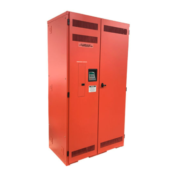
C H A P T E R 3 EFORE NSTALLING THE Installation Dimensions and Clearances Unit #1 1.75-5.0kVA Unit #2 6.25-7.5kVA Unit #3 10.0-16.7kVA 115895B System Installation Manual... - Page 8 Table 3.1 Dimensions Unit #1 (1.75-5.0KVA) Height Unit Depth (A) Width (C) 25” 48” 24” 22.13” 2.06” 2.38” 3.38” 44.75” Cabinet (113.6 cm) (63.5 cm) (61.0 cm) (60.9 cm) (56.2 cm) (5.2 cm) (6.0 cm) (8.6 cm) Extended 56.3" 53.8 Height Option (143 cm)
- Page 9 Location Guidelines Keep the following guidelines in mind when choosing the location for your system and batteries: • Verify that the environment meets the requirements in “Storage and Operating Environment” on page 9. The environment can affect the reliability and performance of both the unit and the batteries.
- Page 10 Ventilation The air around the unit must be clean, dust-free, and free of corrosive chemicals or other contaminants. Do not place the system or batteries in a sealed room or container. Operating Temperature System can operate from 20° to 30°C (68° to 86°F) and up to 95% relative humidity. The batteries’ service life is longer if the operating temperature stays below 25°C (77°F).
-
Page 11: Chapter 4: Installation Overview
C H A P T E R 4 NSTALLATION VERVIEW Figure 4.1 shows typical installations of system. Standard 1.75 kW, 2.5 kW, 3.75 kW, 5.0 kW, 6.25 kW, 7.5 kW, 10.0 kW, 12.5 kW, and 16.7 kW models do not have external battery cabinets. Building Service Supported... -
Page 12: Chapter 5: Ac Input & Ac Output Installation
C H A P T E R 5 AC I & AC O NPUT UTPUT NSTALLATION WARNING Only qualified service personnel (such as a licensed electrician) should perform the AC installation. There is a risk of electrical shock. Read the following cautions before you continue. CAUTION •... - Page 13 Table 5.1 Recommended Circuit Breaker for Maximum Input Current System Input Voltage (Vac) Max. Current Recommended Circuit Breaker 1.75 kW 120V 20 amps 1.75 kW 208V 11 amps 1.75 kW 240V 10 amps 1.75 kW 277V 9 amps 1.75 kW 480V 5 amps 2.5 kW...
- Page 14 5. Write down the circuit breaker value that applies to your system from Table 5.1: __________ 6. Now, look at Table 5.2 below, and use the notes below to find the proper gauge wire for the recommended circuit breaker recorded in step 5. Table 5.2 Recommended Minimum Wire Sizes Read These Important Notes! For this Input...
- Page 15 The next step explains where to make the AC connections to the system. INSTALLING AC INPUT WIRES: 11. Connect AC utility from the service panel to the system’s terminal block labeled “INPUT”. For 2-wire input: connect hot wire to the input block marked “Line”, connect the common wire to the input block marked “Neutral”...
- Page 16 Figure 5.2 AC Connections for 6.25 k W– 7.5 kW systems 115895B System Installation Manual...
- Page 17 Figure 5.3 AC Connections for 10 kW – 16.7 kW systems 115895B System Installation Manual...
-
Page 18: Chapter 6: Installing Batteries And Dc Wiring
C H A P T E R 6 DC W NSTALLING ATTERIES AND IRING WARNING Only qualified service personnel (such as a licensed electrician) should perform the battery and DC wiring installation. There is a risk of electrical shock. This section explains how to install system batteries, fuses, and cables. For all models, you must install the batteries in the system cabinet. - Page 19 A qualified electrician familiar with battery systems and required precautions must install and service the batteries. Any battery used with this unit shall comply with the applicable requirements for batteries in the standard for emergency lighting and power equipment, UL 924 (Canada’s National Building Code). Cabinets are design to be used with, and batteries must be replaced with, manufacturer battery number BAT- CG12105X, BAT-CG12150X OR BAT-CG12180X, see the battery wiring diagram that came with the battery cables.
- Page 20 Before Installing the Batteries Tools CAUTION Always use insulated tools when you work with batteries. Always torque connections to the manufacturer’s recommendations. When you work with system batteries, you need the following tools. The tools must be insulated so they do not short battery terminals to the cabinet. Wear the safety equipment required by local code whenever the doors are open and whenever you are working on batteries.
- Page 21 Location The system batteries belong inside the unit. Before you start installing the batteries, you must install the system in its permanent location. If you have not already done this, see “Location Guidelines” on page 9 to choose a location. CAUTION To prevent damage to your equipment, do not move the system after the batteries are installed.
- Page 22 NOTE: For standard 90-minute runtimes, 1.75 kW, 2.5 kW, 3.75 kW, 5.0 kW, 6.25 kW, 7.5 kW, 10.0kW, 12.5kW, and 16.7kW models have one battery string. 2. Clean the cable connectors with the wire brush before you make the battery connections.
- Page 23 Use the Same Quantity and Type of Battery CAUTION You must use the same quantity and type of battery. Substituting batteries not supplied by manufacturer voids the UL (CUL) listing and may cause equipment damage. To ensure continued superior performance of your system and to maintain proper charger operation, you must replace the batteries in the system with the same number of batteries.
- Page 24 CHAPTER 7 URNING ON THE YSTEM AND ETTING ARAMETERS Several parameters in the system software determine when and how your system conducts the automatic monthly and annual tests. Refer to “User Setup” in the “Front Panel Display” chapter of the system user’s Guide for a description of each test. Starting the Unit Before you can set the parameters, you must start the system.
-
Page 25: Chapter 7: Turning On The System & Setting Parameters
Figure 7.2 Battery Fuse, DC Pre-charge Switch & Installation Switch (6.25 kW – 7.5 kW) (4.69 kW System for 120 Minute run-time) Figure 7.3 Battery Fuse, DC Pre-charge Switch & Installation Switch (10 kW – 16.7 kW) (7.5 kW System for 120 Minute run-time) 115895B System Installation Manual... - Page 26 RONT ANEL ISPLAY The Front Panel Display assembly consists of a 4 x 20 vacuum fluorescent display and a 4-button keypad. The 4 buttons can navigate through all the menus by using the left and right arrow keys, the ENTER and the ESCAPE. The default menu will scroll between the status screen and the Identification/Date-Time screen.
- Page 27 Meter Functions To get to the meter functions from the default screen, press the ENTER key, scroll to the METER menu using the left or the right arrow key, then press the ENTER key again. Use left or the right arrow key to view the meter function desired.
- Page 28 Alarm Log To get the Alarm log menu from the default screen, press the ENTER key, scroll to the alarm log menu using the left or right arrow key, then press the ENTER key again. Use the left or right arrow key to view the alarm desired, and then press the ENTER key for more information.
- Page 29 and then use the left or right arrow key. Once the desired number is reached, press the ENTER key and this will return to the top-level menu. Table 7.3 Near Low Battery Fault Chart DC Voltage Near Low Battery 48VDC 43VDC 72VDC 65VDC...
-
Page 30: Part 2 - Options Manuals
PART II PTIONS ANUALS (Section continues on next page) 115895B System Installation Manual... -
Page 31: Section 1: Bacnet Communication Option Manual
ANUAL INGLE HASE ILLUMINATOR SUPERNOVA MERGENCY IGHTING ENTRAL NVERTER Myers Emergency Power Systems 44 South Commerce Way, Bethlehem, PA 18017 1-800-526-5088 • (610) 868-3500 • Fax: (610) 868-8686 Service: (610) 868-5400 www.myerseps.com 115895B System Installation Manual BACNET COMMUNICATION OPTION SECTION... - Page 32 Table of Contents SECTION 1 ............................ 32 BACnet Communication Option Board ................32 SECTION 2 ............................ 32 Description of Operation ...................... 32 SECTION 3 ............................ 33 Settings ..........................33 Termination, Baudrate and MAC Address: ................ 33 Factory Defaults: ........................33 SECTION 4 ............................
-
Page 33: Bacnet Communication Option Board
SECTION 1 BACnet Communication Option Board The BACnet Communication Option Board for the single-phase Illuminator Supernova Emergency Lighting Central Inverter has two internal connections, the RS232 communication bus and the input power. There are two external connections, a RS485 output connector and a USB connection that is the computer interface. -
Page 34: Settings
File objects include a writable Archive property. Files are used to access one of three dynamic logs of Alarms, Tests and Events. SECTION 3 Settings There are two objects, AV1 and AV2 that will allow the software to change the Baudrate and MAC address respectively. -
Page 35: Object Summary
BI67.Object_Name Output Contact Status 8 SECTION 4 Object Summary objectID object name notes INPUT VOLTAGE OUTPUT VOLTAGE OUTPUT CURRENT A AC AI10 BATTERY VOLTAGE AI11 AMBIENT TEMPERATURE °C AI12 OUTPUT VA (TOTAL) AI13 OUTPUT VA AI16 SYSTEM DAYS days (0..65535) AI17 UPS RUN TIME min (0..65535) -
Page 36: Protocol Implementation
SECTION 5 Protocol Implementation Vendor Name: Myers Power Products, Inc. Product Name: Product Model Number: PCB404303P00 Applications Software Version: v2.00 Firmware Revision: v1.02 BACnet Protocol Revision: BACnet Standardized Device Profile (Annex L) EBI is capable of supporting the B-ASC profile and lower. - Page 37 HASE ILLUMINATOR SUPERNOVA MERGENCY IGHTING ENTRAL NVERTER Myers Emergency Power Systems 44 South Commerce Way, Bethlehem, PA 18017 1-800-526-5088 • (610) 868-3500 • Fax: (610) 868-8686 Service: (610) 868-5400 www.myerseps.com 115895B System Installation Manual BACNET IP & SNMP COMMUNICATION OPTION SECTION...
-
Page 38: Section 2: Bacnet Ip & Snmp Communication Option Manual
Table of Contents Contents SECTION 1 ..............................38 BACNET MS/TP Communication Board ..................38 Babel Buster BB2-7030 ........................39 SECTION 2 ..............................40 Description of Operation .........................40 SECTION 3 ..............................40 Default Ethernet Settings ........................40 Default BACnet IP Settings ......................40 Default SNMP Settings ........................40 SECTION 4 ..............................41 Object Summary ..........................41 Analog Inputs (analog sensors or counters read from the inverter) ......41 Binary Inputs (status flags from the inverter;... -
Page 39: Section 1
BACNET MS/TP Communication Board BACnet IP and SNMP communication from the single-phase Illuminator Supernova Emergency Lighting Central Inverter is achieved via a standard Myers EPS BACnet MS/TP communication board – which converts the RS-232 communication with the inverter controller into the BACnet MS/TP protocol – and a Babel Buster BB2-7030 BACnet MS/TP to BACnet IP Gateway and Router, made by Control Solutions Inc. -
Page 40: Babel Buster Bb2-7030
BACnet IP and/or SNMP. The BB2-7030 is preprogrammed to: • Provide BACnet IP proxy objects to read the values of the BACnet objects presented by the Myers inverter (see Section 4). The proxy objects are updated every 5 seconds • Provide SNMP OIDs to access all BACnet objects, and act as an SNMP... -
Page 41: Section 2
SECTION 2 Description of Operation The single-phase Illuminator Supernova Emergency Lighting Central Inverter acts as a BACnet IP server, and SNMP Agent (server). It supports a total of nine analog objects (floating point on BACnet IP, and rounded to the nearest integer on SNMP), seventeen binary flag objects and three file objects (only accessible when BB2-7030 is in Router Mode). -
Page 42: Section 4
SECTION 4 Object Summary Analog Inputs (analog sensors or counters read from the inverter) Object Name Units SNMP OID Register Input Voltage Volts AC AI 1 1.3.6.1.4.1.3815.1.3.1.1.1.1.2.1 Output Voltage Volts AC AI 4 1.3.6.1.4.1.3815.1.3.1.1.1.1.2.2 Output Current Amps AC AI 7 1.3.6.1.4.1.3815.1.3.1.1.1.1.2.3 Battery Voltage Volts DC... -
Page 43: Section 5
SECTION 5 Connecting to the BB2-7030 Web Server the First Time To be able to do things like change the IP address, set a different BACnet ‘Device Instance’ number, change the SNMP ‘community’ code, or set up SNMP traps, you will first need to connect to the BB2-7030’s web server. Start by directly connecting an Ethernet cable between your PC and the BB2-7030. -
Page 44: Setting Up Ip Address And Lan Settings
Setting up IP Address and LAN Settings Click on the “System Setup” tab. You will be presented with a ‘Sign in’ popup prompt. Type “root” for Username, and “buster” for Password. Now navigate to “System Setup” >> “Setup” >> “Local Host”. The page should look like this: Enter the IP Address that you desire your BB2-7030 to have, and the Subnet Mask and Gateway address for the LAN that the BB2-7030 will be on. -
Page 45: Setting Up Bacnet Ip (Including Device Instance)
By default, the BB2-7030 acts as a BACnet MS/TP to BACnet IP gateway (proxy) for one device (the single Myers EPS inverter system). In the unlikely case that you wish to configure it to be a BACnet router, see the section below on Gateway vs Router. - Page 46 4. Set the value. For analog objects, use any value. For binary objects, use “0” to trap on a logic 0, or “1” to trap on a logic 1. 5. For analog values, consider setting a hysteresis. For example, if you are programming a trap for when ambient temperature is greater than 30°C, you might want to put in a hysteresis of 2°C so that if the temperature is right on the 30°C mark and oscillating with small variations over and...
-
Page 47: Saving And Activating Your Changes
Finally, refer to the “Saving and Activating Your Changes” subsection below to make your programming changes permanent (otherwise, they may be lost if the inverter loses power for long enough for the entire battery to deplete, or if maintenance is performed on the inverter). Saving and Activating Your Changes Any changes you make on the BB2-7030 web pages - other than changing IP address - are temporary. - Page 48 RS-485 wiring (RS-485 is the physical layer of BACnet MS/TP), and/or systems with 3 party (non-Myers) BACnet MS/TP devices, but where BACnet IP integration is also required. This system topology is illustrated in Figure 4: 115895B System Installation Manual BACNET IP &...
- Page 49 (it has 3 screw terminals ; see Figure 2 in Section 1) while keeping the wires that connect to the BB2-7030 also connected. 2. Myers Emergency Power Systems cannot take responsibility for or assist in the behavior / programming / operation of 3 party (non-Myers) BACnet devices sharing the network.
-
Page 50: Configuring Bb2-7030 As A Router
(marked Inverter ‘N’ in Figure 4 above) will be preconfigured to act as a BACnet Gateway, it will have an (inactive) XML file already loaded into it (from Myers EPS manufacturing) that reconfigures the device to be a BACnet Router instead, along with some manual steps on the ‘BACnet IP Port’... -
Page 51: On Network Numbers
• Enter the allocated network numbers for the BACnet IP Network (on the Ethernet side of this BB2-7030), and for the MS/TP Network (on the MS/TP RS-485 side of this BB2-7030). See the section below marked “On Network Numbers” for more detailed information. •... -
Page 52: Alarm Logs
Alarm Logs This is an example of an Alarm Log file: 19/08/21 09:31 INVERTER FAULT 19/08/25 22:14 LOW VAC • Each line in the file begins with a timestamp in the format “YY/MM/DD HH:MM”. Note that the time is in 24-hour format. Note also that the time must be set up correctly in the inverter control board, or the timestamps will be wrong. -
Page 53: Test Logs
• The final field provides the recorded output current (in Amps) • The next field describes the recorded temperature, in degrees Celsius • Each line ends with a DOS style line ending (“\r\n”) Please contact Myers EPS Service at if you have questions or (610) 868-5400 concerns. - Page 54 INGLE HASE ILLUMINATOR SUPERNOVA MERGENCY IGHTING ENTRAL NVERTER Myers Emergency Power Systems 44 South Commerce Way, Bethlehem, PA 18017 1-800-526-5088 • (610) 868-3500 • Fax: (610) 868-8686 Service: (610) 868-5400 www.myerseps.com 115895B System Installation Manual MODBUS SERIAL COMMUNICATION OPTION SECTION...
-
Page 55: Section 3 Modbus Serial Communication Option Manual
Table of Contents SECTION 1 ..............................55 MODBUS Serial Comm Option Board - Introduction ................55 SECTION 2 ..............................56 Description of Operation ........................56 SECTION 3 ..............................56 Settings ..............................56 RS-485 connection, Serial Mode, Parity, Baudrate and Slave Address: .........56 MODBUS Slave Address Settings ....................57 Serial Communication Information ......................59... -
Page 56: Modbus Serial Comm Option Board - Introduction
SECTION 1 MODBUS Serial Comm Option Board - Introduction The MODBUS Communication Option Board for the single-phase Illuminator Supernova Emergency Lighting Central Inverter has two internal connections; the RS232 communication bus to the inverter controller, and the input power that powers the board. There are two external connections, a RS485 output connector that is the MODBUS link, and a USB connection that is a serial computer interface into the RS232 communication bus to the inverter controller. -
Page 57: Description Of Operation
SECTION 2 Description of Operation The MODBUS Communication Option Board acts as a MODBUS slave. It supports both the RTU (binary) and ASCII modes of MODBUS Over Serial Line. For both modes, it supports either Even Parity or No Parity, and four baud rates: 9600bps, 19,200bps, 38,400bps and 115,200bps. -
Page 58: Modbus Slave Address Settings
MODBUS Slave Address Settings MODBUS Slave Address is set on SW1, an 8-position DIP switch. The tables below describe the possible address settings: MODBUS Slave Addresses 1 – 63 MODBUS Slave Addresses 64 – 127 Address Address 8 7 6 5 4 3 2 1 8 7 6 5 4 3 2 1 ON ON ON ON ON ON ON ON 247 (0xF7) ON OFF ON ON ON ON ON ON... - Page 59 MODBUS Slave Addresses 128 – 191 MODBUS Slave Addresses 192 – 247 Address Address 8 7 6 5 4 3 2 1 8 7 6 5 4 3 2 1 OFF ON ON ON ON ON ON ON 128 (0x80) OFF OFF ON ON ON ON ON ON 192 (0xC0) OFF ON ON ON ON ON ON OFF 129 (0x81) OFF OFF ON ON ON ON ON OFF 193 (0xC1)
-
Page 60: Serial Communication Information
Serial Communication Information • MODBUS Slave Address: 1 to 247 (selectable by DIP) • Communication Mode: MODBUS RTU or MODBUS ASCII (selectable by DIP) • Parity: Even or None (selectable by DIP) • Baud Rate: 9600, 19200, 38400 or 115200 (selectable by DIP) •... -
Page 61: Object Summary (Registers And Coils)
SECTION 4 Object Summary (Registers and Coils) The sixteen-bit registers can be accessed via either MODBUS Function Code 3 (0x03 Read Holding Registers) or Function Code 4 (0x04 Read Input Registers). Results will be identical. The flag objects can be accessed via either MODBUS Function Code 1 (0x01 Read Coils) or Function Code 2 (0x02 Read Discrete Inputs). -
Page 62: Biasing, Link Load And Link Termination
SECTION 5 Biasing, Link Load and Link Termination The MODBUS Communication Option Board includes weak (10kΩ) pull-up and pull-down resistors on the MODBUS RS-485 link for the purpose of link biasing. Therefore, external link biasing on the bus is not required when at least one MODBUS Communication Option Board is connected on the bus segment. -
Page 63: Setting A Custom User Id
Setting a Custom User ID Setting a Custom User ID is done with MODBUS Function Code 0x15 (Write File Record). See the description of the Write File Record function code in the MODBUS Application Protocol Specification document from http://www.modbus.org/specs.php • Sub Request Reference Type must be 0x06 •... -
Page 64: Requesting Identification With 'Report Server Id' (0X11)
Requesting Identification With ‘Report Server ID’ (0x11) The first way to request identification from the MODBUS Communication Option Board is with MODBUS Function Code 0x11 (Report Server ID). The MODBUS Communication Option Board will respond with an ASCII string that contains: •... -
Page 65: Example
Reading a log is done with MODBUS Function Code 0x14 (Read File Record). See the description of the Read File Record function code in the MODBUS Application Protocol Specification document from http://www.modbus.org/specs.php • Sub Request Reference Type must be 0x06 •... - Page 66 o 0x0001 is the File Number (for the Alarm Log File) o 0x0000 is the Record Number (we’re starting to read the file from byte 0) o 0x0020 (32) is the Record Length. We wish to read the first 32 bytes of the file.
- Page 67 o 0x2F (47) is the file read response length (including the Reference Type byte) o 0x06 is the Reference Type (fixed) o The last 46 bytes of the PDU are byte pairs. If you eliminate all the (0x00 valued) most significant bytes of each byte pair, you are left with the ASCII data read out of the Alarm Log file: 39 2f 30 38 2f 32 35 09 32 32 3a 31 34 09 4c 4f 57 20 56 41 43 0D 0A...
-
Page 68: Parsing File Records (Alarm, Event And Test Logs)
Parsing File Records (Alarm, Event and Test Logs) This section will describe the information contained in Alarm, Event and Test log files, and how to parse them. Alarm Logs This is an example of an Alarm Log file: 19/08/21 09:31 INVERTER FAULT 19/08/25 22:14... -
Page 69: Test Logs
Test Logs This is an example of a Test Log file: 19/08/15 02:45 277.9 10.8 28.0 19/08/30 23:00 276.1 10.6 27.6 • Each line in the file begins with a timestamp in the format “YY/MM/DD HH:MM”. Note that the time is in 24-hour format. Note also that the time must be set up correctly in the inverter control board, or the timestamps will be wrong. - Page 70 HASE ILLUMINATOR SUPERNOVA MERGENCY IGHTING ENTRAL NVERTER Myers Emergency Power Systems 44 South Commerce Way, Bethlehem, PA 18017 1-800-526-5088 • (610) 868-3500 • Fax: (610) 868-8686 Service: (610) 868-5400 www.myerseps.com 115895B System Installation Manual MODBUS TCP & SNMP COMMUNICATION OPTION SECTION...
-
Page 71: Section 3: Modbus Tcp & Snmp Communication Option Manual
Table of Contents SECTION 1 ..............................71 MODBUS Serial Communication Board ....................71 Babel Buster BB2-6010..........................72 SECTION 2 ..............................73 Description of Operation ........................73 SECTION 3 ..............................73 Default Ethernet Settings ........................73 Default MODBUS TCP Settings ......................73 Default SNMP Settings ..........................73 SECTION 4 ..............................74 Object Summary .............................74 SECTION 5... -
Page 72: Modbus Serial Communication Board
MODBUS Serial Communication Board MODBUS TCP and SNMP communication from the single-phase Illuminator Supernova Emergency Lighting Central Inverter is achieved via a standard Myers EPS MODBUS serial communication option board – which converts the RS-232 communication with the inverter controller into the MODBUS RTU protocol – and a Babel Buster BB2-6010 MODBUS RTU to MODBUS TCP Gateway, made by Control Solutions Inc. -
Page 73: Babel Buster Bb2-6010
Babel Buster BB2-6010 The Babel Buster BB2-6010 is a DIN-rail mounted protocol bridge that is pre-programmed to convert between MODBUS RTU and MODBUS TCP and/or SNMP. It features two external connectors; one for MODBUS RTU RS485 and power in (24 Volts AC or DC), and the other for Ethernet (LAN connection) out. Figure 2 is a diagram of the BB2-6010. -
Page 74: Description Of Operation
SECTION 2 Description of Operation The single-phase Illuminator Supernova Emergency Lighting Central Inverter acts as a MODBUS TCP server, and SNMP Agent (server). It supports a total of nine analog objects (sixteen-bit integers), and seventeen binary flag objects. It can also be programmed to transmit SNMP ‘traps’ when a programmed condition is met (analog value goes above or below a threshold value, or binary flag gets set to 1 or cleared to 0). -
Page 75: Object Summary
SECTION 4 Object Summary All registers below are accessible via either MODBUS Function Code 3 (0x03 Read Holding Registers) using the specified register address, or SNMP ‘Get’ / ‘Get Next’ using the specified SNMP OID. Register / Object Name Units SNMP OID Analog Values (analog sensors or counters read from the inverter) Input Voltage... - Page 76 1.3.6.1.4.1.3815.1.2.2.1.1.1.1.1.2.143 Register / Object Name Units SNMP OID Inverter Failure 0 (false) or 1 (true) (0x008F) 1.3.6.1.4.1.3815.1.2.2.1.1.1.1.1.2.144 Near Low Battery 0 (false) or 1 (true) (0x0090) 1.3.6.1.4.1.3815.1.2.2.1.1.1.1.1.2.145 In Load Reduction 0 (false) or 1 (true) (0x0091) 1.3.6.1.4.1.3815.1.2.2.1.1.1.1.1.2.146 Inverter Runtime Failure 0 (false) or 1 (true) (0x0093) 1.3.6.1.4.1.3815.1.2.2.1.1.1.1.1.2.148...
-
Page 77: Connecting To The Bb2-6010 Web Server The First Time
SECTION 5 Connecting to the BB2-6010 Web Server the First Time To be able to do things like change the IP address, change the SNMP ‘community’ code, or set up SNMP traps, you will first need to connect to the BB2-6010’s web server. -
Page 78: Setting Up Ip Address And Lan Settings
Setting Up IP Address and LAN Settings Click on the “System” tab. You will be presented with a ‘Sign in’ popup prompt. Type “root” for Username, and “buster” for Password. Now navigate to “System Setup” >> “Setup” >> “Network”. The page should look like this: Enter the IP Address that you desire your BB2-6010 to have, and the Subnet Mask and Gateway address for the LAN that the BB2-6010 will be on. -
Page 79: Setting Up Modbus Tcp
When done, click the “Change IP” button to save your changes. Wait at least 15 seconds until the settings are changed and the webpage reloads. Now cycle power to your BB2-6010 by pulling out and then re-inserting the “MODBUS RTU and Power In” connector. At this point, if you wish you may disconnect the direct ethernet connection between your PC and the BB2-6010 and put it on the LAN and connect to it through the LAN via its new IP address setting. - Page 80 The first step in programming a trap is to program a ‘Threshold’ rule (a rule that when true, will send a trap). To program a ‘Threshold’ rule, first navigate to the following web page: “System” >> “Action Rules” >> “Thresholds” . Initially, there is just one threshold rule, and it is blank.
- Page 81 Once you have programmed all your desired rules, the next step is to make them generate traps. The BB2-6010 lets you send traps to up to three different groups of “Trap Receivers” (in case you want some traps to go to one destination, and other traps to go to another).
-
Page 82: Saving And Activating Your Changes
To download and save the xml file, press Ctrl-S (⌘-s on an Apple) or right click on white space on the page and click “Save As”. Please contact Myers Service at if you have questions or concerns. (610) 868-5400 115895B System Installation Manual MODBUS TCP &... - Page 83 RS-232 Communications Illuminator Supernova Users Manual 115895B System Installation Manual SERIAL TO ETHERNET ADAPTER OPTION SECTION...
-
Page 84: Section 4: Rs-232 Communications Manual
TABLE OF CONTENTS Introduction ..............................84 Connection..............................84 Terminal Settings ............................85 Commands ..............................85 Shell Command ............................85 Help screen ..............................86 Version ..............................86 Alarm Setpoint ............................86 Meter Functions ............................87 Status .................................87 Alarms ...............................88 Alarms, Events, and Tests Dump ......................88 Date and Time ............................91 LOCATION OF THE RS232 PORT FOR “E” & “IE” 6-16.7k ..............92 LOCATION OF THE RS232 PORT FOR “E”... -
Page 85: Introduction
(such as Tera Term, PuTTy, xterm, etc.), or by any embedded device capable of RS-232 serial communication. We shall call this device the Client. The protocol used is proprietary, and specific to Myers EPS’ Emergency Lighting Central Inverters. CONNECTION The Central Inverter has a 9-pin Sub-D (DB9) female connector typically located on the back (inside) of the front display panel located on the door of the inverter. -
Page 86: Terminal Settings
TERMINAL SETTINGS Baud Rate: 19,200 Data Bits: Parity: None Stop Bits: Flow Control: None Character Set: ANSI The Illuminator Supernova RS-232 protocol uses carriage returns (‘\r’, ANSI code 0x0D), but does not use line feeds (‘\n’, ANSI code 0x0A). If you are manually typing commands, some terminal emulator software will automatically feed the line back when you press enter (and a carriage return is sent) and when the inverter responds (with a response string followed by a carriage return). -
Page 87: Help Screen
Help screen You may type “help” at the command prompt for a listing of various commands available. CMD>help Display current firmware version. set point Display or modify set points. meter Display meter values. status Display present status. alarms Display alarms. dump Dump logs (alarms, tests, events). -
Page 88: Meter Functions
For example, to turn on the low voltage alarm when the input voltage goes below 105 VAC, type “lvac” and then press tab and type”105” and then tab and then type “on” and press enter. CMD>setpoint lvac The other set points can be changed in the same manner. Meter Functions To read Voltages and currents, the meter command may be used. -
Page 89: Alarms
Alarms The alarm status of the machine is available through the “alarms” command. When the alarm command is typed, the following information is available. CMD>alarms Inverter Charger Output Overload Overload Shutdown: 0 High Ambient High VAC Low VAC Low Battery Near Low Battery : 0 Utility Load Reduction... - Page 90 The dump command must be followed by a tab and then either “alarms”, “tests” or “events” as the second field. After pressing the ‘enter’ key, the inverter will display a “Press Enter when ready…” prompt. Press the ‘enter’ key once again, and the inverter will dump out the specified log. Note that this log may be several kilobytes in size and will be streamed out in one go.
- Page 91 Do not forget to stop capture after data is transferred. Press Enter when ready... ***********< TEST LOGS >*********** 1/75 MONTHLY 09/20/19 17:43 DURATION : 5 MIN FAULTS VOUT : 125.3 IOUT : 7.5 TEMP : 33.5 deg C 75/75 MONTHLY 03/15/14 08:30 DURATION : 5 MIN FAULTS...
-
Page 92: Date And Time
Date and Time The date and time can be viewed by typing the “dt” command. When dt is sent, the interface sends back the date and time information. Each parameter of the date and time are assigned a number. The dt command produces the following message: CMD>dt (1) day of week : 1..7 (2) month : 1..12... -
Page 93: Location Of The Rs232 Port For "E" & "Ie" 6-16.7K
LOCATION OF THE RS232 PORT FOR “I” 1.75-5.0K LOCATION OF THE RS232 PORT FOR “I” 6.25 –7.5K 115895B System Installation Manual SERIAL TO ETHERNET ADAPTER OPTION SECTION... -
Page 94: Location Of The Rs232 Port For "Em" 1.0 - 2.8K
LOCATION OF THE RS232 PORT FOR “I” 10.0 – 16.7K 115895B System Installation Manual SERIAL TO ETHERNET ADAPTER OPTION SECTION... - Page 95 115895B System Installation Manual SERIAL TO ETHERNET ADAPTER OPTION SECTION...
- Page 96 115895B System Installation Manual SERIAL TO ETHERNET ADAPTER OPTION SECTION...
-
Page 97: The Zoom Modem (Optional)
THE ZOOM MODEM (OPTIONAL) Configuring the ZOOM Modem (optional) Connect the 9VDC Power Adapter Connect the PC serial port to the modem’s serial port On the PC, bring up a terminal communications program such as HyperTerminal. Configure your terminal emulator software to the following: 19,200 BPS 8 Data Bits No Parity... - Page 98 Serial to Ethernet Adapter Quick Start Manual Myers Emergency Power Systems 44 South Commerce Way, Bethlehem, PA 18017 1-800-526-5088 • (610) 868-3500 • Fax: (610) 868-8686 Service: (610) 868-5400 www.myerseps.com 115895B System Installation Manual SERIAL TO ETHERNET ADAPTER OPTION SECTION...
-
Page 99: Section 5: Serial To Ethernet Adapter Quick Start Manual
Serial to Ethernet Communication Interface – QuickStart Guide The Serial to Ethernet Communication Interface primarily allows you to monitor and control your Myers EPS Emergency Lighting Central Inverter over an SSH connection (on port 2222) using the Myers EPS RS-232 Communication Protocol. The SSH port number can be configured, or if you choose, Telnet may be selected instead of SSH. - Page 100 Your Serial to Ethernet Communication Interface is now ready for SSH communication with your Myers EPS Emergency Lighting Central Inverter, using the IP address you set in Section 1 above, and SSH on port 2222. If you would like to change...
- Page 101 Use “myerseps” as the username, and “inverter” as the password. You should now be connected to your Myers EPS Emergency Lighting Central Inverter, and ready to communicate with it using the Myers EPS RS-232 Communication Protocol, as described in the RS-232 Protocol Manual. To find the right RS-232 Protocol Manual in PDF format: •...
- Page 102 6. Change the port number to your desired value in the box labeled “Listed for connections on TCP Port” 7. Click the “Apply” button 8. Click the “Reboot IOLAN” button that just appeared in the bottom right. After the IOLAN SDG1 reboots (give is 60 seconds), it will accept SSH connections on the new port number you specified.
- Page 103 YSTEM PTION ANUAL MERGENCY IGHTING ENTRAL NVERTER Myers Emergency Power Systems 44 South Commerce Way, Bethlehem, PA 18017 1-800-526-5088 • (610) 868-3500 • Fax: (610) 868-8686 Service: (610) 868-5400 www.myerseps.com 115895B System Installation Manual BATTERY THERMAL RUNAWAY SYSTEM OPTION SECTION...
-
Page 104: Section 6: System Options Manual Battery Thermal Runaway
Table of Contents SECTION 1 ..............................104 System Description ..........................104 Power Supply/Summary Relay PCB connections ..............104 Temperature Sensor PCB Connections: ..................105 System Schematic: ..........................106 SECTION 2 ..............................106 Description of Operation ........................106 LED Definitions ...........................107 SECTION 3 ..............................108 System Installation ..........................108 115895B System Installation Manual BATTERY THERMAL RUNAWAY SYSTEM OPTION SECTION... -
Page 105: System Description
SECTION 1 System Description The Thermal Runaway Detection Option consists of two components. The first PCB component is the Power Supply Relay PCB that performs a summary dry contact closure on an alarm from any of the temperature sensor boards. This PCB is shown in Picture 1. -
Page 106: Temperature Sensor Pcb Connections
-40°C to 125°C**. The wire length of the temperature probes can be cut to any length without adversely affecting the temperature accuracy. **Note – Only use Myers Emergency Power Systems supplied temperature probes (Part# RE-THER2100I). Picture 2 – Temperature Sensor PCB... -
Page 107: System Schematic
System Schematic: Figure 1 shows a schematic of the power supply and temperature sensor PCB and the connections. The schematic shows a two temperature sensor board system with four temperature probes connected to each monitoring board but there are many other different possible configurations. Dry contacts are setup for normally open configuration. -
Page 108: Led Definitions
If a battery is in a thermal runaway condition there are four indications that will result. The four conditions will remain in a latched state until the reset button is depressed for a few seconds and then released. 1) The summary alarm contact will be activated. 2) The audible summary alarm will be activated on the temperature sensor pcb with the battery that is in a thermal runaway condition. -
Page 109: System Installation
SECTION 3 System Installation 1) Power Supply/Summary Relay – The PCB’s will be installed in the Emergency Lighting Inverter Electronics Cabinet. Dependant on the number of batteries there may be more than one power supply presenting the electronics module please refer to Battery Thermal Runaway drawing specific to the Emergency Lighting Inverter System Installed. - Page 110 Picture 3 Brown Black Picture 4 2) Temperature Sensor PCB – The PCB’s will be mounted in the battery cabinets of the Emergency Lighting Inverter. If the batteries are in the same cabinet as the electronics then it will be mounted in the electronics/battery cabinet.
- Page 111 b. The power and error signal connections will need to be wired from the first Temperature Sensor PCB to the next Temperature sensor PCB via the wire supplied in the kit. This will follow the instruction in item a until the last temperature sensor pcb has been wired. c.
- Page 112 Use supplied Velcro in kit and attach it to the plastic box. See diagram for location placement. Figure 2 – Stripped Probe leads insert into connectors 115895B System Installation Manual BATTERY THERMAL RUNAWAY SYSTEM OPTION SECTION...
- Page 113 PART III RAWINGS (Drawings section continues on next page) 115895B System Installation Manual DRAWINGS SECTION...
-
Page 114: Part 3 - Drawings
115895B System Installation Manual DRAWINGS SECTION... -
Page 115: Battery Interconnect
115895B System Installation Manual DRAWINGS SECTION... - Page 116 115895B System Installation Manual DRAWINGS SECTION...
- Page 117 115895B System Installation Manual DRAWINGS SECTION...
- Page 118 115895B System Installation Manual DRAWINGS SECTION...
- Page 119 115895B System Installation Manual DRAWINGS SECTION...
- Page 120 115895B System Installation Manual DRAWINGS SECTION...
- Page 121 115895B System Installation Manual DRAWINGS SECTION...
- Page 122 115895B System Installation Manual DRAWINGS SECTION...
- Page 123 115895B System Installation Manual DRAWINGS SECTION...
-
Page 124: Output Breakers
115895B System Installation Manual DRAWINGS SECTION... - Page 125 115895B System Installation Manual DRAWINGS SECTION...
-
Page 126: Remote Meter Panel
115895B System Installation Manual DRAWINGS SECTION... -
Page 127: Remote Summary Alarm Panel
115895B System Installation Manual DRAWINGS SECTION... -
Page 128: Inverter On Dry Contacts
115895B System Installation Manual DRAWINGS SECTION... -
Page 129: Summary Dry Contacts
115895B System Installation Manual DRAWINGS SECTION... -
Page 130: Multi Form C Dry Contacts
115895B System Installation Manual DRAWINGS SECTION... -
Page 131: Wiring Diagram Ul1008 Transfer Relay
Notes: 115895B System Installation Manual...
Need help?
Do you have a question about the Illuminator Supernova Series and is the answer not in the manual?
Questions and answers