Table of Contents
Advertisement
Quick Links
Advertisement
Table of Contents

Subscribe to Our Youtube Channel
Related Manuals for GBC TITAN 165


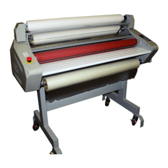
Summary of Contents for GBC TITAN 165
- Page 1 TITAN 165 / 110 Laminating Systems Instruction Manual...
- Page 2 TITAN 165 / 110 TECHNICAL SERVICE MANUAL © October 2000 GBC Films Group Do not duplicate without written permission. GBC Pro - Tech 4151 Anderson Road DeForest, WI 53532 Revision : Ph: ( 608 ) 246 - 8844 Fx: ( 608 ) 246 - 8645...
- Page 3 The information in this publication is provided for reference and is believed to be accu- rate and complete. GBC Films Group is not liable for errors in this publication or for incidental or consequential damage in connection with the furnishing or use of the information in this publication, including, but not limited to, any implied warranty of fitness or merchantability for any particular use.
- Page 4 Read me file Titan 165/ 110 Technical Service Manual This page intentionally left blank. © GBC Films Group October 2000...
- Page 5 From : Company : Address : Phone number : ( Fax number : ( Re : Titan 165/ 110 Technical Service Manual ( 930 - 054 ) Section #: Page #: Correction (s): Additional comments: © GBC Films Group October 2000...
- Page 6 Read me file Titan 165/ 110 Technical Service Manual This page intentionally left blank. © GBC Films Group October 2000...
-
Page 7: Table Of Contents
Titan 165/ 110 Technical Service Manual Table of Contents Table of Contents 1.0 Safety 1.1 Service schedule ..................1 - 1 1.2 Cleaning the rollers ..................1 - 2 1.3 Clean the cabinets and covers ..............1 - 5 1.4 Cleaning the control panel .................1 - 5 1.5 Lubrication ....................1 - 6... - Page 8 5.1 Chain is snapping ..................5 - 2 5.2 Unwind brakes do not work ...............5 - 3 6.0 Schematics Titan 165 ( 220 volt ) ..................6 - 2 Titan 110 ( 220 volt ) ..................6 - 3 Page II © GBC Films Group October 2000...
- Page 9 Titan 165/ 110 Technical Service Manual Table of Contents 7.0 Spare parts 7.1 Item list .......................7 - 1 8.0 Illustrated parts 8.1 Titan 165 Stand and frame assembly ................8 - 2 Slitter and cooling cover assembly ..............8 - 3 Idlers and rollers assembly ................8 - 4 Drive side assembly ..................8 - 5...
- Page 10 Table of Contents Titan 165/ 110 Technical Service Manual 8.2 Titan 110 Stand and frame assembly ................8 - 13 Slitter and cooling cover assembly ..............8 - 14 Idlers and rollers assembly ................8 - 15 Drive side assembly ..................8 - 16 Cabinets and rear cover assembly ..............8 - 17...
-
Page 11: Service Schedule
• Check the rewind chain tension. • Any commissioning or service engineer must be ( The only chain that can be of competent nature, trained and qualified to GBC Pro- Tech standards to fulfill that job. This person will have tensioned ) completed and passed the full service training course from GBC Pro-Tech. -
Page 12: Cleaning The Rollers
Servicing Titan 165/ 110 Technical Service Manual Semi-Annual 1.2 Cleaning the rollers • Lubricate sprockets and chains. Tools required ( See Lubrication in this section ) • Protective rubber gloves ( protect your hands from the isopropyl alcohol ) • 80% isopropyl alcohol... - Page 13 Titan 165/ 110 Technical Service Manual Servicing a) Turn the MAIN POWER to the “ I ” position. CAUTION Do NOT pick or pull heat activated adhesive off the rolls when they are cold. You can W A R N IN G cause irreparable damage to the laminating rolls.
- Page 14 Servicing Titan 165/ 110 Technical Service Manual W A R N IN G C A U T IO N W h en op erating th e lam inator u sin g the Footsw itch sp eed is lim ited w h en th e safety footsw itch, keep hand s and fin gers aw ay shield is in the raised position or rem oved .
-
Page 15: Clean The Cabinets And Covers
Titan 165/ 110 Technical Service Manual Servicing 1.3 Clean the cabinets and 1.4 Cleaning the control covers panel ELECTRICAL ELECTRICAL S H O C K S H O C K Remove power from the laminator before Remove power from the laminator before cleaning. -
Page 16: Lubrication
Servicing Titan 165/ 110 Technical Service Manual b) Use a small flat tip screw driver to remove the 1.5 Lubrication contact block from the emergency stop button. E L E C T R IC AL S H O C K R em ove pow er from the lam inator before servicing. -
Page 17: Calibrations
Titan 165/ 110 Technical Service Manual Calibrations 2.0 Calibrations 2.1 Main roller nip This calibration ensures the main rollers nip is even W AR N IN G from left to right. Main roller nip should be performed at time of installation. - Page 18 Calibrations Titan 165/ 110 Technical Service Manual d) Inspect the nip impression in the web of the h) Use the small flat tip screw driver to remove the laminate for eveness across the entire width. If contact block to the emergency stop buttons.
-
Page 19: Pull Roller Nip
Titan 165/ 110 Technical Service Manual Calibrations 2.2 Pull roller nip IN F O R M A T IO N A ny w aves in the lam inate and/ or w aves at This calibration ensures the pull rollers nip is even the m ain roller nip constitute poor output. -
Page 20: Clutch Adjustment
Calibrations Titan 165/ 110 Technical Service Manual f) Use the small flat tip screw driver to remove the 2.3 Clutch adjustment contact block to the emergency stop buttons. This calibration adjusts the tension of the web g) Use the small flat tip screw driver to remove the between the main rollers and the pull rollers. -
Page 21: Temperature Calibration
Titan 165/ 110 Technical Service Manual Calibrations c) With a #2 phillips head screw driver, remove the 2.4 Temperature calibration drive side cabinet. This calibration adjusts the temp displays d) Use the small flat tip screw driver to remove the to properly reflect the heater temperatures. - Page 22 Calibrations Titan 165/ 110 Technical Service Manual d) Use the small flat tip screw driver to remove the contact block to the emergency stop button. e) With a #2 phillips screw driver, remove the rear IN F O R M AT IO N panel cover.
-
Page 23: Changing Parts
R em ove pow er from the lam inator before manual can be provided within a reasonable time. Please servicing. Y ou can be severely shocked, contact the GBC Technical Service Center at 1-888- electrocuted or cause a fire. 231-2211 for assistance. - Page 24 Parts changing Titan 165/ 110 Technical Service Manual d) Disconnect the contact block to the emergency 3.1.1 Remove the cabinets stop push button using a flat tip screw driver and set the control side cabinet in a safe place. Tools required •...
- Page 25 Titan 165/ 110 Technical Service Manual Parts changing c) While the second person is holding the drive 3.1.2 Replace the cabinets side cabinet, connect the contact block to the emergency stop push button. Tools required d) Have the second person align the holes of the drive side cabinet with the holes on the side •...
-
Page 26: Heaters
Parts changing Titan 165/ 110 Technical Service Manual c) Remove the nut securing the heater wire to the 3.2 Heaters end of the heater being removed using an 8 mm wrench. Do this for both sides. W AR N IN G d) Use the 8 mm wrench to remove the nut securing the heater to the heater support plate. - Page 27 Titan 165/ 110 Technical Service Manual Parts changing 3.2.2 Replacing the heater(s) C AU T IO N E nsure the nut is secure on the heater! a) If installing new heaters, remove the two nuts and L oose connection m ay cause...
-
Page 28: Upper Rollers
Parts changing Titan 165/ 110 Technical Service Manual b) Remove the pressure plate by pulling in on the 3.3 Upper rollers two locator pins. Tools required c) Remove the front feed table by pulling on the safety pin located under the table on the drive (left) side of the machine from the front opoerating position. - Page 29 Titan 165/ 110 Technical Service Manual Parts changing f) Control side only: With a #2 phillips head screw i) Remove the main roller and pull roller port plates driver, remove the upper bolt securing the lift plate using a 4 mm allen wrench.
- Page 30 Parts changing Titan 165/ 110 Technical Service Manual e) Secure the lift plate spring and tighten the phillips 3.3.2 Replacing the upper roller(s) head bolt using a #2 phillips head screw driver. a) Carefully replace the roller from the control side f) Replace the washer and bolt to the lift plate guide of the machine.
-
Page 31: Lower Rollers
Titan 165/ 110 Technical Service Manual Parts changing c) Remove the front feed table by pulling on the safety 3.4 Lower rollers pin located under the table on the drive (left) side of the machine from the front opoerating position. - Page 32 Parts changing Titan 165/ 110 Technical Service Manual j) Carefully remove the chains and sprockets associated with the lower rollers. IN F O R M AT IO N If your chain has a m aster link, you k) With a #2 phillips head screw driver, remove the m ay rem ove the chain by disconnecting upper bolt securing the lift plate spring.
- Page 33 Titan 165/ 110 Technical Service Manual Parts changing f) Replace the washer and bolt to the lift plate guide 3.4.2 Replacing the lower roller(s) and secure in place with the #2 phillips head screw driver.. a) Replace the lower roller bearings on both ends of the roller.
- Page 34 Parts changing Titan 165/ 110 Technical Service Manual This page intentionally left blank. Page 3 - 12 © GBC Films Group October 2000...
-
Page 35: Flowcharts - Electrical
C AU T IO N Please refer to section 6.0 for full schematics. The Titan 165 and Titan 110 are identical electronically O nly the prim ary person ( person with the exception of one extra cooling fan on the perform ing the troubleshooting ) m ay Titan 165. -
Page 36: Machine Will Not Power On
Flowcharts - Electrical Titan 165/ 110 Technical Service Manual 4.1 Machine will not power on Check Incoming power to the laminator (230vac) If voltage is not present at the input for the circuit breaker have an electrician check the building circuit. - Page 37 P R O P R IE T A R Y G B C P R O - T E C H C L A IM S P R O P R IE T A R Y R IG H T S T O T H E M A T E R IA L D IS C L O S E D O N T H IS D R A W IN G .
-
Page 38: No Heaters
Flowcharts - Electrical Titan 165/ 110 Technical Service Manual 4.2 No heaters Check the power to the heaters (230vac) Disconnect and test the voltage (230vac) at con 10 for the top heater and at con 12 for the bottom heater. If the correct voltage is not present replace the main PCB. - Page 39 P R O P R IE T A R Y G B C P R O - T E C H C L A IM S P R O P R IE T A R Y R IG H T S T O T H E M A T E R IA L D IS C L O S E D O N T H IS D R A W IN G .
-
Page 40: No Cooling Fans
Flowcharts - Electrical Titan 165/ 110 Technical Service Manual 4.3 No cooling fans Check power to the fans(230vac) Disconnect and check the output from the main PCB board at the terminals labeled FAN (230vac). If voltage is not present then replace the main PCB board. - Page 41 P R O P R IE T A R Y G B C P R O - T E C H C L A IM S P R O P R IE T A R Y R IG H T S T O T H E M A T E R IA L D IS C L O S E D O N T H IS D R A W IN G .
-
Page 42: No Motor
Flowcharts - Electrical Titan 165/ 110 Technical Service Manual 4.4 No motor Check to see if the foot switch will activate the motor. If the foot switch functions then go to step 2 If the foot switch does not work then go to step 3 Check the roller cover switches. - Page 43 Titan 165/ 110 Technical Service Manual Flowcharts - Electrical Check the power transformer. Disconnect and check for 34vac at the connector labeled 34vac on the main PCB board. If 34vac is not present then check the fuse located to the right of the main PCB.
- Page 44 Flowcharts - Electrical Titan 165/ 110 Technical Service Manual This page intentionally left blank. Page 4 - 10 © GBC Films Group October 2000...
- Page 45 P R O P R IE T A R Y G B C P R O - T E C H C L A IM S P R O P R IE T A R Y R IG H T S T O T H E M A T E R IA L D IS C L O S E D O N T H IS D R A W IN G .
- Page 46 Flowcharts - Electrical Titan 165/ 110 Technical Service Manual This page intentionally left blank. Page 4 - 12 © GBC Films Group October 2000...
-
Page 47: Flowcharts - Mechanical
Titan 165/ 110 Technical Service Manual Flowcharts - Mechanical 5.0 Flowcharts - Mechanical C AU T IO N A lw ays practice lock out/ tag out procedures w hen perform ing service related w ork. Mechanical troubleshooting consist of checking bushings, chains, sprockets and idlers. -
Page 48: Chain Is Snapping
Flowcharts - Mechanical Titan 165/ 110 Technical Service Manual 5.1 Chain is snapping C h a in is sn ap p in g S ec u re s et s e t s cre w s o n s c re w s o n s p ro c k ets s h a ft. - Page 49 Titan 165/ 110 Technical Service Manual Flowcharts - Mechanical 5.2 Unwind brakes are not working. U n w in d b ra k e s a re n o t w o rk in g C h a n g e th e c o re...
- Page 50 Flowcharts - Mechanical Titan 165/ 110 Technical Service Manual This page intentionally left blank. Page 5 - 4 © GBC Films Group October 2000...
- Page 51 6.0 Schematics In this section you will find the electrical schematic for the Titan 165 and the Titan 110. The only difference between the two schematics is that the Titan 165 is equipped with three fans and the Titan 110 only has two.
- Page 52 P R O P R IE T A R Y G B C P R O - T E C H C L A IM S P R O P R IE T A R Y R IG H T S T O T H E M A T E R IA L D IS C L O S E D O N T H IS D R A W IN G .
- Page 53 P R O P R IE T A R Y G B C P R O - T E C H C L A IM S P R O P R IE T A R Y R IG H T S T O T H E M A T E R IA L D IS C L O S E D O N T H IS D R A W IN G .
- Page 54 Technical Schematics Blank page This page intentionally left blank. Page 6 - 4 © GBC Films Group October 2000...
- Page 55 Titan 165/ 110 Technical Service Manual Recommended Spare Parts 7.0 Spare Parts This is a recommended spare parts list and can be modified as required. The quantity is based on one machine. Consult your service manager if you require spare parts for more than one machine.
- Page 56 Recommended Spare Parts Titan 165/ 110 Technical Service Manual Part # Description 704031124 Power cord ( US ) 704030416 Power cord ( Euro ) 704090603 Footswitch 701130507 Casters 704090252 Emergency switch 613030613 Feed table latch 701110203 Plate washer 601230814 Lever guide...
- Page 57 Titan 165/ 110 Technical Service Manual Recommended Spare Parts Part # Description 604022032 Paper guide knob, 2700 613030622 Roller cover safety lever 613030614 Lever cap 703040211 Teflon bushing © GBC Films Group October 2000 Page 7 - 3...
- Page 58 Recommended Spare Parts Titan 165/ 110 Technical Service Manual This page intentionally left blank. Page 7 - 4 © GBC Films Group October 2000...
- Page 59 8.0 Illustrated Parts Items not illustrated ; This section contains parts illustrations for both the Titan 165 and Titan 110 machines. Section 8.1 contains illustrations for the Titan 165 and section 8.2 contains Operations Manual: 930 - 046 illustrations for the Titan 110.
- Page 60 Illustrated Parts Titan 165/ 110 Technical Service Manual PART # DESCRIPTION Quanity 6090205 DC GEARED MOTOR(DM012) 8050112 57MM 601211157 SURE BACK COVER SUPPORT 601230109 1670RS BOTTOM PLATE 601230231 1670RS SIDE PLATE(L) 601230232 1670RS SIDE PLATE(R) 601230411 1670RS FRONT COVER 601230412...
- Page 61 Titan 165/ 110 Technical Service Manual Illustrated Parts PART # DESCRIPTION Quanity 601230711 SURELAM OUTER TENSION DISC 601230712 COLD OUTSIDE TENSION DISK 601230814 EAGLE LEVER FIXED PANEL 601230834 EAGLE SPRING CAP 601230873 COLD BLADE RAIL BRACKET(L) 601230874 COLD BLADE RAIL BRACKET(R)
- Page 62 Illustrated Parts Titan 165/ 110 Technical Service Manual PART # DESCRIPTION Quanity 613030579 1670RS H/ROLLER BUSH(UP) 613030580 1670RS H/ROLLER BUSH(LOW) 613030587 1670RS FILM TENSION BLOCK 613030597 TENSION BOLT(PL) 613030621 LEVER (UP) 613030622 LEVER (DOWN) 613030631 1670RS GUIDE BUSH PIN 613030632...
- Page 63 Titan 165/ 110 Technical Service Manual Illustrated Parts PART # DESCRIPTION Quanity 701130507 CASTER 703020216 1670RS CONTROL PANEL 703020511 PC CONTROL KEY 703020512 PC CONTROL KEY 703020513 PC CONTROL KEY 703020514 PC CONTROL KEY 703020515 PC CONTROL KEY 703020516 PC CONTROL KEY...
- Page 64 Illustrated Parts Titan 165/ 110 Technical Service Manual PART # DESCRIPTION Quanity 803040356 EAGLE PRESSURE STICKER (L) 803040357 EAGLE PRESSURE STICKER (U) 706025043 HEATER T-110 607040523 HEAT ROLLER T-110 607040524 PULL ROLLER T-110 604036014 FEED TABLE T-110 601230456 SAFEETY SHIELD T-110...
- Page 65 Titan 165/ 110 Technical Service Manual Illustrated Parts © GBC Films Group October 2000 Page 8 - 7...
- Page 66 Illustrated Parts Titan 165/ 110 Technical Service Manual Page 8 - 8 © GBC Films Group October 2000...
- Page 67 Titan 165/ 110 Technical Service Manual Illustrated Parts © GBC Films Group October 2000 Page 8 - 9...
- Page 68 Illustrated Parts Titan 165/ 110 Technical Service Manual Page 8 - 10 © GBC Films Group October 2000...
- Page 69 Titan 165/ 110 Technical Service Manual Illustrated Parts © GBC Films Group October 2000 Page 8 - 11...
- Page 70 Illustrated Parts Titan 165/ 110 Technical Service Manual Page 8 - 12 © GBC Films Group October 2000...
- Page 71 Titan 165/ 110 Technical Service Manual Illustrated Parts © GBC Films Group October 2000 Page 8 - 13...
- Page 72 Illustrated Parts Titan 165/ 110 Technical Service Manual Page 8 - 14 © GBC Films Group October 2000...
- Page 73 Titan 165/ 110 Technical Service Manual Illustrated Parts © GBC Films Group October 2000 Page 8 - 15...
- Page 74 Illustrated Parts Titan 165/ 110 Technical Service Manual Page 8 - 16 © GBC Films Group October 2000...
- Page 75 Titan 165/ 110 Technical Service Manual Illustrated Parts 8.2 Titan 110 Parts illustrations © GBC Films Group October 2000 Page 8 - 17...
- Page 76 Illustrated Parts Titan 165/ 110 Technical Service Manual Page 8 - 18 © GBC Films Group October 2000...
- Page 77 Titan 165/ 110 Technical Service Manual Illustrated Parts © GBC Films Group October 2000 Page 8 - 19...
- Page 78 Illustrated Parts Titan 165/ 110 Technical Service Manual Page 8 - 20 © GBC Films Group October 2000...
- Page 79 Titan 165/ 110 Technical Service Manual Illustrated Parts © GBC Films Group October 2000 Page 8 - 21...
- Page 80 Illustrated Parts Titan 165/ 110 Technical Service Manual Page 8 - 22 © GBC Films Group October 2000...
- Page 81 Titan 165/ 110 Technical Service Manual Addendum 9.0 Addendum This section is reserved for future changes related to this service manual. © GBC Films Group October 2000 Page 9 - 1...
- Page 82 Addendum Titan 165/ 110 Technical Service Manual This page intentionally left blank. Page 9 - 2 © GBC Films Group October 2000...
- Page 83 Control side: refers to the right hand side of Any GBC Technician, GBC Specialist, the machine from the front operating position. and / or GBC Pro-Tech Technician that has been through the GBC Pro-Tech service training course. Drive side: refers to the left side of the machine from the front operating position.
- Page 84 Glossary of terminology Titan 165/ 110 Technical Service Manual This page intentionally left blank. Page 10 - 2 © GBC Films Group October 2000...
Need help?
Do you have a question about the TITAN 165 and is the answer not in the manual?
Questions and answers