Table of Contents
Advertisement
Quick Links
Advertisement
Table of Contents

Related Manuals for GBC Arctic Titan 1040WFC


Summary of Contents for GBC Arctic Titan 1040WFC
- Page 1 GBC Arctic Titan 1040WFC Wide Format Cold Laminator - 3600230 Instruction Manual...
-
Page 2: Cover
Artic Titan 1040/1064 WF c LAMINATOR INSTALLATION & OPERATION MANUAL Document Number: 930-136 Do not duplicate without written permission. Installation and Operating Manual Part Number: Rev. 07-26-06... -
Page 3: Legal Disclaimer
GBC reserves the right to make changes to this publication and to the products described in it without notice. All specifications and information concerning products are subject to change without notice. Reference in this publication to information or products protected by copyright or patent does not convey any license under the rights of GBC or others. -
Page 4: Table Of Contents
Removing and Installing the Feed TABLE OF CONTENTS Table Loading Film onto the Supply Shaft Description Page Loading Film with a Threading Card Loading Film by Tacking New Film to Existing Film Decaling in Two Passes Cover Mounting Tips for Threading Pressure Sensitive Legal Disclaimer Adhesive (PSA) Film Pre-Treating Boards... -
Page 5: Important Safety Instructions
IMPORTANT SAFETY INSTRUCTIONS IMPORTANT SAFEGUARDS YOUR SAFETY AS WELL AS THE SAFETY OF WARNING: TO GUARD AGAINST INJURY OTHERS IS IMPORTANT BEFORE YOU INSTALL THE FOLLOWING SAFETY PRECAUTIONS OR USE THE MACHINE, READ AND FOLLOW ALL MUST BE OBSERVED IN INSTALLATION THE SAFETY NOTICES CAREFULLY IN THIS AND USE OF THE LAMINATOR. -
Page 6: Warranty
LIMITED 90- DAY WARRANTY repaired, altered, moved, or installed by anyone other than GBC warrants to the original purchaser for a period of ninety GBC or its authorized agents; or if incompatible film was days on labor and one year on parts after installation that this used. -
Page 7: Specifications
SPECIFICATIONS Artic Titan 1040 WF c Artic Titan 1064 WF c Operating Speed • 0 to 189 fpm(0.8 to 4 0to 18 fpm(0.8 to 4 m) Variable • 3fpm (0.9 m) 3fpm (0.9 m) Fixed Dimensions • Width 54 in (137 cm) 72.25 in (184 cm) •... -
Page 8: Fcc Note
FCC NOTE FCC Class A Notice - Notification pour les Etats-Unis Note: This equipment has been tested and found to comply with the limits for a Class A digital device, pursuant to part 15 of the FCC rules. These limits are designed to provide reasonable protection against harmful interference when the equipment is operated in a commercial environment. -
Page 9: Installation
INSTALLATION This chapter describes how to install the machine. There are no operator serviceable parts to the machine other than periodic cleaning. Refer to the Operator Maintenance chapter. WARNING: Do not attempt to service or repair the laminator. Failure to observe this warning could result severe personal injury or death. -
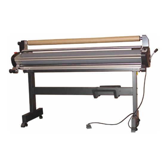
Page 10: Features Guide
FEATURES GUIDE This chapter helps you identify the main components of the laminator. Release liner take-up Top film shaft (Not Shown) Idler Pressure roller Control panel Safety sensor Roller pressure handle Feed table Feed table interlock latch (under table) Idler Bottom supply shaft Bottom supply shaft Food switch... -
Page 11: Safety Sensors
SAFETY SENSORS A. Safety Sensor (Figure 5-2) infrared safety sensors prevent entanglement, entrapment, and inadvertent contact with the rollers. The sensors are located on each side of the machine, in front of the bottom roller. They stop the machine when a hand or object blocks the invisible infrared beam if you are not using the foot switch. -
Page 12: Bottom Film Supply Shaft
BOTTOM FILM SUPPLY SHAFT Holds the film or kraft paper on the machine. FILM WEB (Not shown.) The path the laminating film and/or mounting film mounted on the machine takes through the machine. CORE ADAPTORS A. Supply shaft (Figure 5-5) B. -
Page 13: Tension Adjustment Knobs And Motor
TENSION ADJUSTMENT KNOBS AND MOTOR A. Rewind Motor (Figure 5-7) B. Film Tension Adjustment Knobs (Figure 5-7) Fig. 5-7. Artic Titan 1040 WF c Tension Adjustment Knobs and Motor A. Rewind Tension Adjustment Knob (Figure 5-8) B. Film Tension Adjustment Knobs (Figure 5-8) The film supply shaft tension knobs allow the operator to increase or decrease the film web tension as needed to reduce curl and wrinkles. -
Page 14: Control Panel
CONTROL PANEL A. Speed Adjustment (Figure 5-10) Turn the speed adjustment knob to set the desired speed. It is adjustable from 0Ft/mn to 18Ft/mn (0.8 to 4 B. LED WARNING: Keep your fingers and hands away from the nip point (the point where the upper and lower rollers meet). -
Page 15: Operation
OPERATION This chapter describes how to use the laminator to: • Operate the machine • Load films (web the machine) • Laminate items • Mount items GENERAL OPERATION These instructions assume that the films have been loaded. For information about loading films, see the Loading Film section in this chapter. -
Page 16: Loading Film
LOADING FILM The Artic Titan 1040 WF c and Artic Titan 1064 WF c laminators runs poly-in and poly-out pressure sensitive adhesive (PSA) films. Poly-in means the adhesive side of the film is on the inside of the film roll. Poly-out means the adhesive is on the outside of the film roll. -
Page 17: Removing And Installing The Print Clamp (Artic Titan 1064 Wf C)
REMOVING AND INSTALLING THE The print clamp guides prints into the rollers. It should be PRINT CLAMP (Artic Titan 1064 WF c) removed when mounting items to thicker boards. It also needs to be removed to install films and when cleaning the rollers. -
Page 18: Loading Film Onto The Supply Shaft
LOADING FILM ONTO THE SUPPLY SHAFTS If you are loading film for the first time, skip these instructions and start with the instructions, To load films onto the supply shafts. If you are replacing existing films, perform the following set of instructions, To remove existing films. - Page 19 To load films onto the supply shafts: (Figure 6-9) A. Supply shaft B. Take-up shaft C. Core Adaptors D. Gripper If the supply shaft is on the machine, grasp the bearing end and lift it out of the cradle. Then pull the left end out of the brake hub.
-
Page 20: Loading Film With A Threading Card
LOADING FILM WITH A THREADING CARD The following procedure uses a film threading card that is sometimes provided with new rolls of film. If one is not provided, a scrap of cardboard or poster board with a straight edge is suitable. Either can be reused. Prior to loading film, remove the print clamp (Artic Titan 1064 WF c) and feed table. -
Page 21: Loading Film By Tacking New Film To Existing Film
LOADING FILM BY TRACKING NEW The following describes a method for loading film whereby FILM TO EXISTING FILM the existing film on the rollers may be used in place of the threading card to draw the new film through the laminator. Leading edges of the new film will be overlapped onto the adhesive of the old film. -
Page 22: Decaling In Two Passes
DECALING IN TWO PASSES Decaling is where you laminate items and then mount them on other materials such as Foam Core or mounting board. It is performed in two passes. The first pass laminates and applies the mounting adhesive, encapsulating the item. The second pass mounts it on rigid material. -
Page 23: Mounting
MOUNTING TIPS FOR THREADING PRESSURE SENSITIVE ADHESIVE (PSA) FILM • Use kraft paper for one-sided lamination. • Refer to Fig. 6-17 for the proper film configuration. • Whenever possible, pull the remaining web of film out the front of the laminator after the finished item has been removed. -
Page 24: Film Tension
FILM TENSION Proper film tension, known as brake tension, is the minimum amount required to eliminate wrinkles in the finished item. As the film roll becomes smaller, tension increases, thus the adjustment needs to be loosened. Film tension should be checked occasionally to assure that the adjustment is correct. -
Page 25: Testing The Web
TESTING THE WEB After webbing the machine, it is important that the films run straight and evenly. To test the web: Set the roller pressure handle to an appropriate position. Press RUN or the foot switch and run approximately 6 in. (10 cm) of laminate. Press STOP or release the foot switch. -
Page 26: Operator Maintenance
OPERATOR MAINTENANCE CARING FOR THE Artic Titan 1040 WF c OR 1064 WF c LAMINATOR The only maintenance required by the operator is to periodically clean the rollers. The following procedure will help keep them free of dirt and adhesive, which has been deposited along the edge of the laminating film. Proper alignment of the rolls of film reduces the amount of adhesive on the rollers. -
Page 27: Troubleshooting
TROUBLESHOOTING SYMPTOM POSSIBLE CAUSE CORRECTIVE ACTION Power lamp does not illuminate on Laminator not connected to electrical Insert attachment plug into receptacle. the control panel when the ON/OFF supply. switch is in the ON position. Rollers do not turn. Infrared eyes blocked. Unblock infrared eyes.
Need help?
Do you have a question about the Arctic Titan 1040WFC and is the answer not in the manual?
Questions and answers