Table of Contents
Advertisement
Quick Links
Advertisement
Table of Contents

Related Manuals for Fronius ACCTIVA PROFESSIONAL FLASH 70A


Summary of Contents for Fronius ACCTIVA PROFESSIONAL FLASH 70A
- Page 1 / Perfect Charging / Perfect Welding / Solar Energy Operating instructions Acctiva Professional Flash UCN US / CN 充电器 Battery charging system 42,0426,0199,EN 004-15042021 Fronius prints on elemental chlorine free paper (ECF) sourced from certified sustainable forests (FSC).
-
Page 3: Safety Rules
Safety rules Explanation of DANGER! safety notices Indicates immediate danger. ▶ If not avoided, death or serious injury will result. WARNING! Indicates a potentially hazardous situation. ▶ If not avoided, death or serious injury may result. CAUTION! Indicates a situation where damage or injury could occur. ▶... - Page 4 General remarks The charger is manufactured in line with the latest state of the art and according to recognised safety standards. If used incorrectly or misused, however, it can cause injury or death to the user or a third party, damage to the charger and other material assets belonging to the operator, inefficient operation of the charger.
-
Page 5: Dangers From Mains Current And Charging Cur- Rent
This may affect a number device types in terms of: Connection restrictions Criteria with regard to the maximum permissible mains impedance Criteria with regard to the minimum short-circuit power requirement at the interface with the public grid see "Technical data" In this case, the plant operator or the person using the device should check whether the device may be connected, where appropriate by discussing the matter with the power supply company. -
Page 6: General Informa- - Tion Regarding The - Handling Of Bat- Teries
Battery acid must not get into the eyes or onto the skin or clothes. Wear protective goggles and suitable protective clothing. Rinse any acid splashes thoroughly with clean water and seek medical advice if necessary. General informa- Protect batteries from dirt and mechanical damage. tion regarding the Store charged batteries in a cool place. -
Page 7: Maintenance And Repair
EMC measures In certain cases, even though a device complies with the standard limit values for emis- sions, it may affect the application area for which it was designed (e.g. when there is sensitive equipment at the same location, or if the site where the device is installed is close to either radio or television receivers). - Page 8 Disposal Do not dispose of this device with normal domestic waste! To comply with the European Directive on Waste Electrical and Electronic Equipment and its implementation as national law, electrical equipment that has reached the end of its life must be collected separately and returned to an approved recycling facility.
- Page 9 General Safety WARNING! Risk of injury and damage from exposed, rotating vehicle parts. When working in the vehicle’s engine compartment, take care that hands, hair, items of clothing and charger leads do not come into contact with moving parts, e.g. fan belt, fan, etc.
-
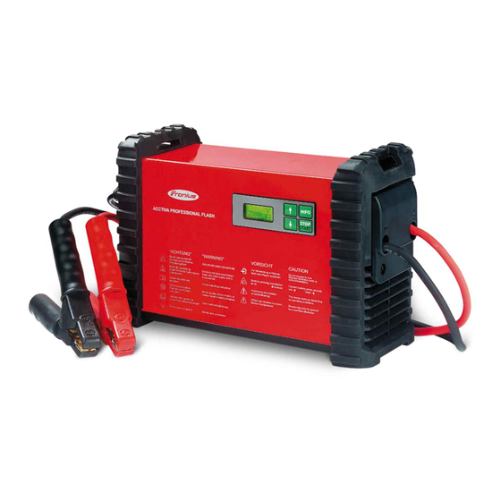
Page 10: Control Elements And Connections
(-) charging terminal - black (+) charging terminal - red USB port For updating the firmware. For further details please see our Internet homepage http://www.fronius.com (4) (5) Front view Multifunction panel Devices equipped with main switch Mains cable/plug Rear view... - Page 11 (10) Info button For setting the desired mode for retrieving charging parameters during charging (11) Start/Stop button For interrupting and restarting charging (12) „Down“ button (13) „Up“ button (14) (13) (12) (11) (10) (14) Display Multifunction panel...
-
Page 12: Fitting Options
Fitting options Fitting optional Depending on the device, a special edge guard can be fitted. edge guard IMPORTANT! The edge guard must be fitted if the charger is being mounted on a wall, as the fitting tools assume that an edge guard is present. The edge guard must not be fitted if the charger is installed on the floor. - Page 13 Fasten the wall bracket to a suitable wall surface using dowels and screws Position charger on wall bracket The base of the charger must lie flat on the wall bracket. Only if the charger is being fitted per- manently to the wall bracket: Fasten the charger to the bracket using the two screws supplied (dia- meter 3.5 x 9.5 mm)
-
Page 14: Operating Modes
Operating modes Available operat- Overview of available operating modes. ing modes Important additional information on the individual operating modes can be found in the following sections. Standard charging For batteries with liquid electrolyte (Pb, GEL, Ca, Ca sil- ver) For batteries with fixed electrolyte (AGM, MF, sealant) Refresh charging For reactivating batteries with liquid electrolyte (Pb, GEL, Ca, Ca silver) - Page 15 NOTE! refresh charging may only be used when: ▶ the battery capacity has been correctly set ▶ refresh charging takes place in a well-ventilated area User charging User charging is an additional charging mode in which charging parameters for the mode device can be specified individually.
-
Page 16: Charging The Battery
Charging the battery Starting charging CAUTION! Risk of damage when attempting to charge a faulty battery. Before charging, ensure that the battery to be charged is fully functional. CAUTION! When refresh charging is selected: risk of damage of the on-board electronics by refresh charging. - Page 17 Retrieving para- Press the info button during charging meters during charging The actual charging current is displayed: E.g.: actual charging current By repeated pressing the info button, the other parameters are displayed in the following sequence: E.g.: actual battery E.g.: amount of charge fed in E.g.: energy fed in voltage E.g.: length of time char-...
- Page 18 Connect (+) charging terminal to positive pole on battery Connect (-) charging terminal to negative pole on the battery, or to vehicle body (e.g. engine block) in the case of vehicle electrical systems. Press start/stop button for approx. 5 secs A query regarding correct polarity of the charging terminals is displayed: Starting the charging process confirms the correct polarity connection.
- Page 19 Interrupting char- Press Start/Stop button to interrupt charging ging / resuming charging Press Start/Stop button again to resume charging Self test E.g.: charging continues Retrieving para- Charging was interrupted by pressing the start/stop button. meters when charging has Press the info button stopped The actual charging current is displayed: E.g.: actual charging current...
- Page 20 Finishing char- WARNING! ging and discon- necting the bat- Risk of explosion due to sparkinhg when disconnecting the charging terminals. tery Before disconnecting the charging terminals, stop charging by pressing the start/stop button and possibly provide adequate ventilation. Finish charging by pressing the start/stop button Disconnect (-) charging terminal from battery Disconnect (+) charging terminal from battery...
-
Page 21: External Power Supply
External power supply Starting the external power supply Select FSV/SPLY mode by pressing the info button Connect (+) charging terminal to positive pole on battery Connect (-) charging terminal to negative pole on the battery, or to vehicle body (e.g. engine block) in the case of vehicle electrical systems Charger detects that the battery is connected, carries out a self test and starts external power supply. - Page 22 Connect (+) charging terminal to positive pole on battery Connect (-) charging terminal to negative pole on the battery, or to vehicle body (e.g. engine block) in the case of vehicle electrical systems press start/stop button for approx. 5 secs A query regarding correct polarity of the charging terminals is displayed: Starting the external power supply confirms the correct polarity connection.
- Page 23 By pressing the info button, the parameters are displayed in the following sequence: actual charging current actual battery voltage amount of charge (Ah) fed in so far energy (Wh) fed in so far length of time charging so far Disconnect (-) charging terminal from battery Disconnect (+) charging terminal from battery...
- Page 24 Charge acceptance test General Charge acceptance test mode is used to determine a battery’s ability to accept a charge. The charge acceptance test takes place as follows: charge acceptance testing is conducted automatically for a period of 15 minutes; if the result is positive, the device will then switch automatically to standard charging mode and charge the battery if the result is negative, „Test Fail“...
- Page 25 Charger detects that the battery is connected, carries out a self-test and starts the charge acceptance test. Self test Charge acceptance test Starting the CAUTION! charge accept- ance test manu- Risk of serious damage if the charging terminals are connected incorrectly. ally The reverse polarity protection facility is inoperative if the current input test is started manually (battery voltage <...
- Page 26 the top half of the display features progress bars to show the progress of the current charging operation the bottom half of the display shows the current charging parameters / calculated test parameters E.g.: actual charging current By repeated pressing the info button, the other parameters are displayed in the following sequence: Charging parameters: E.g.: actual battery voltage...
- Page 27 E.g.: battery voltage E.g.: set battery capacity E.g.: Battery’s capacity to accept charge, expressed in % If the terminals are disconnected from the battery in this mode, the charger reverts to the Operating Mode menu.
-
Page 28: Setup Menu
Setup menu General remarks The setup menu gives you the ability to configure the device’s basic settings according to your own requirements. You can also store frequently used charge settings. WARNING! Operating the equipment incorrectly can cause serious damage. The functions described must only be carried out by trained and qualified personnel. In addition to the safety rules in these operating instructions, the safety rules of the battery and vehicle manufacturers must also be followed. - Page 29 Accessing setup To access menu: press info button for approx. 5 secs menu Select menu item using the „up“ and „down“ buttons Enter the selected menu item by pressing the start/stop button IMPORTANT! If no selection is made within 30 seconds, the setup menu is exited auto- matically.
- Page 30 Parameters in the USER U/I menu maximum charging current (standard charging) Setting range: see Technical Data, in steps of 0,5 A main charging voltage (standard charging) setting range: 12.0 - 15.5 V, in steps of 0.1 V conservation charging voltage (standard charging) setting range: Off / 12.0 - 15.5 V, in steps of 0.1 V IMPORTANT! the conservation charging voltage is only available in Charge mode.
- Page 31 IMPORTANT! Conservation charging does not take place if conservation charging is set to OFF. However, if the battery voltage drops below 12 V, charging starts. safety cut-out (user charging) setting range: 2 h - 30 h, in 10 min intervals IMPORTANT! If charging does not end automatically after the set time has elapsed, the charger will be switched off as a safety precaution..
- Page 32 Select one of the following operating modes using the „up“ and „down“ buttons Preferred Setting Used Mode (factory setting) After disconnecting the charging terminals or mains supply, the last mode selected is saved. Preferred Setting: charge acceptance test mode After disconnecting the charging terminals or mains supply, the charge acceptance test mode is saved.
- Page 33 The length of the charger cable flashes. Set the length of the charger cable using the „up“ and „down“ buttons Setting range: 1 to 25 m (3 ft. 3 in. to 82 ft.) To save the length of the charger cable press the start/stop button Select the cross-section of the charger cable using the „up“...
- Page 34 Device has been reset to factory setting. The submenu is exited automatically. DELAY TIME menu - setting the delay time The delay time flashes. Set the desired delay time using the „up“ and „down“ buttons Setting range: 0 - 4 h To save the delay time press the start/stop button IMPORTANT! Delay time must be set again after each cycle.
- Page 35 DEVICE HISTORY menu - querying operating hours Select one of the following views using the „up“ and „down“ buttons Operating Hours Shows the operating hours (device connected to the mains or switched on) Charging Hours Displays the operating time (time during which the device has been producing power) Cumulated Ampere Hours Displays the amount of charge produced...
-
Page 36: Troubleshooting
Troubleshooting Troubleshooting Charging terminals connected to wrong poles Cause Charging terminals connected to wrong poles Remedy Swap charging terminals round Charging terminals short-circuited Cause Short-circuit on the charging terminals Remedy Rectify short-circuit on the charging terminals Cause Battery not detected Remedy Check that charging terminals are properly connected, press Start/Stop button for 5 seconds... - Page 37 Cause Fan blocked Remedy Check air inlet, remove foreign bodies if necessary Cause Fan faulty Remedy Contact specialist dealer Fuse faulty Cause Secondary fuse faulty Remedy Contact specialist dealer Charger faulty Cause Charger faulty Remedy Contact specialist dealer Nothing on display Cause Mains supply interrupted Remedy...
-
Page 38: Symbols Used
Symbols used Warning notices Follow operating instructions affixed to the charger Connect battery poles correctly: (+) red (-) black Detonating gas is generated in the battery during charging. Risk of explosion! The charger heats up depending on operating conditions. Before disconnecting the charger lead from the battery, interrupt charging. Chargers may only be opened by a qualified electrician Avoid flames and sparks during charging. -
Page 39: Technical Data
Technical data Acctiva Profes- Mains voltage (+/- 15%) sional Flash, Acctiva Professional Flash 230 V AC, 50/60 Hz Acctiva Profes- Acctiva Professional Flash AUS 240 V AC, 50/60 Hz sional Flash AUS, Acctiva Professional Flash JP 100 V AC, 50/60 Hz Acctiva Profes- Acctiva Professional 30A JP 100 V AC, 50/60 Hz... - Page 40 FRONIUS INTERNATIONAL GMBH Froniusstraße 1 A-4643 Pettenbach AUSTRIA contact@fronius.com www.fronius.com Under www.fronius.com/contact you will find the addresses of all Fronius Sales & Service Partners and locations...
Need help?
Do you have a question about the ACCTIVA PROFESSIONAL FLASH 70A and is the answer not in the manual?
Questions and answers