Table of Contents
Advertisement
Quick Links
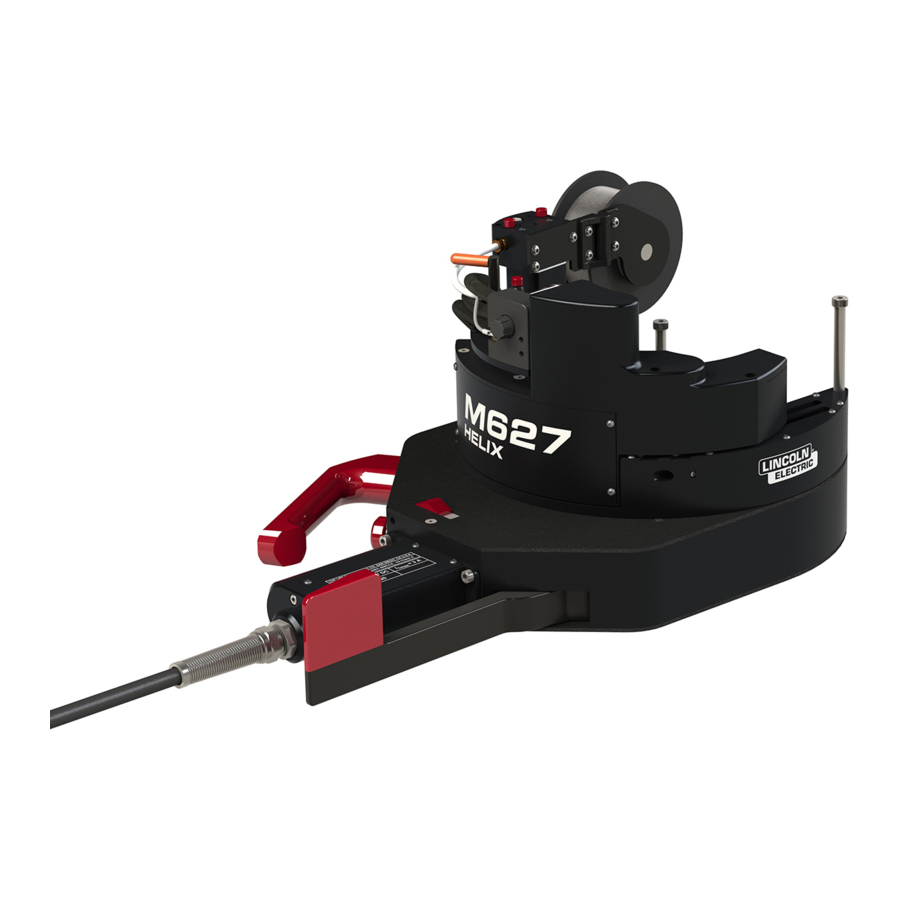
Operator's Manual
HELIX
M627 WELD HEAD
®
Register your machine:
www.lincolnelectric.com/register
Authorized Service and Distributor Locator:
www.lincolnelectric.com/locator
Save for future reference
Date Purchased
Code: (ex: 12735)
Serial: (ex: U1060512345)
IM10606
| Issue D ate Apr-21
© Lincoln Global, Inc. All Rights Reserved.
For use with machines having Code Numbers:
13139
Need Help? Call 1.888.935.3877
to talk to a Service Representative
Hours of Operation:
8:00 AM to 6:00 PM (ET) Mon. thru Fri.
After hours?
Use "Ask the Experts" at lincolnelectric.com
A Lincoln Service Representative will contact you
no later than the following business day.
For Service outside the USA:
Email: globalservice@lincolnelectric.com
ORIGINAL INSTRUCTIONS
c/o Balmes, 89 - 8
2
0
a
08008 Barcelona
SPAIN
Advertisement
Table of Contents

Related Manuals for Lincoln Electric HELIX M627


Summary of Contents for Lincoln Electric HELIX M627
- Page 1 Operator’s Manual HELIX M627 WELD HEAD ® ORIGINAL INSTRUCTIONS For use with machines having Code Numbers: 13139 Need Help? Call 1.888.935.3877 Register your machine: to talk to a Service Representative www.lincolnelectric.com/register Authorized Service and Distributor Locator: Hours of Operation: www.lincolnelectric.com/locator 8:00 AM to 6:00 PM (ET) Mon.
- Page 2 HELIX M627 WELD HEAD SAFETY ® THANK YOU FOR SELECTING A QUALITY PRODUCT BY KEEP YOUR HEAD OUT OF THE FUMES. DON’T get too close to the arc. LINCOLN ELEC TRIC. Use corrective lenses if necessary to stay a reasonable distance away from the arc.
- Page 3 W117.2-1974. A Free copy of “Arc Welding Safety” booklet E205 is available from the Lincoln Electric Company, 2.d. All welders should use the following procedures in order to 22801 St. Clair Avenue, Cleveland, Ohio 44117-1199.
- Page 4 HELIX M627 WELD HEAD SAFETY SAFETY ® ELECTRIC SHOCK ARC RAYS CAN BURN. CAN KILL. 3.a. The electrode and work (or ground) circuits are 4.a. Use a shield with the proper filter and cover plates to protect your electrically “hot” when the welder is on. Do eyes from sparks and the rays of the arc when welding or not touch these “hot”...
- Page 5 HELIX M627 WELD HEAD SAFETY SAFETY ® WELDING AND CUTTING CYLINDER MAY EXPLODE IF SPARKS CAN CAUSE DAMAGED. FIRE OR EXPLOSION. 7.a. Use only compressed gas cylinders containing the correct shielding gas for the process used 6.a. Remove fire hazards from the welding area. If and properly operating regulators designed for this is not possible, cover them to prevent the welding sparks the gas and pressure used.
- Page 6 Electromagnetic Compatibility (EMC) Product Standard for Arc Welding should be electrically continuous throughout its length. The shielding should Equipment. It is for use with other Lincoln Electric equipment. It is designed be connected to the welding power source so that good electrical contact is for industrial and professional use.
- Page 7 HELIX M627 WELD HEAD SAFETY ®...
-
Page 8: Table Of Contents
HELIX M627 WELD HEAD ® TABLE OF CONTENTS Technical Specifications HELIX M627 WELD HEAD ................A-1 Safety Precautions ........................... A-2 Proper handling ............................. A-2 Operation ............................... A-2 HELIX M627 WELD HEAD ......................... A-3 Basic Information ........................... A-3 Basic Components ..........................A-3 Body Assembly ............................ -
Page 9: Technical Specifications Helix M627 Weld Head
HELIX M627 WELD HEAD INSTALLATION ® Technical Specifications HELIX M627 Weld Head HELIX M627 Weld head Product Number K52283-1 Input Power 24 VDC Radial Clearance (around 6.625 in pipe) 6.19" with On Board Feeder Axial Clearance 8.31" Total Depth 6.84" - 7.84"... -
Page 10: Safety Precautions
Verify that the system is properly grounded before Proper Handling beginning to weld. The HELIX M627 weld head is only meant to be picked up and supported by the handles. Only attempt to attach the weld head to the work surface while the clamp mechanism is disengaged and the height is fully retracted. -
Page 11: Helix M627 Weld Head
Basic Information M627 weld head. It contains the travel gears and clamping mechanism. This assembly contains several The Helix M627 weld head is a precision, digitally adjustments and controls, see Figure 2 – Body Assembly Adjustments. controlled weld head for TIG welding. Designed to work... -
Page 12: Torch Motion Assembly
HELIX ® M627 WELD HEAD INSTALLATION Clamp Jaw Portion of the lever mechanism that secures TORCH MOTOR WIRE against the pipe, opposite the clamp shoe, HOUSING GUIDE which tightens the head onto the work BOARD surface. WIRE Lever Arm FEEDER Manipulated by the operator, this lever engages the clamp jaw. -
Page 13: Cable Assembly
HELIX ® M627 WELD HEAD INSTALLATION JUMPER HOSE Cable Assembly AVC SENSE GAS HOSE TORCH POWER/COOLING The cable assembly attaches from the weld head to the MOTOR COOLING controller and power supply. It supplies the input controls, power, gas, and water to the weld head. See Figure 6 – STRAIN Cable Assembly. -
Page 14: Installation
HELIX ® M627 WELD HEAD INSTALLATION 1.9" (48.26mm) 2.38" (60.452mm) K52093-190 K52093-238 2.88" (73.152mm) 3.5" (88.9mm) K52093-288 K52093-350 Figure 9 - Shoe Size 1.9 4" (101.6mm) 4.5" (114.3mm) K52093-400 K52093-450 5.56" (141.224mm) 6.63" (168.402mm) K52093-556 K52093-663 Figure 11 - Standard Clamp Shoe Size Installation Figure 10 - Shoe Size 6.625 HOT SURFACE WARNING! Verify that enough time has... -
Page 15: Removal
HELIX M627 WELD HEAD INSTALLATION ® CLAMP SHOE RELEASE Figure 14 - Weld Head Placement Figure 12 - Shoe Release TUNGSTEN Some elements have been hidden for clarity. Figure 15 - Tungsten Positioning CLAMP SHOE 1.9" CLAMP SHOE INSTALLATION Weld Head Installation DIRECTION With the appropriate clamp shoe selected and the weld head in Figure 13 - Shoe Placement... -
Page 16: Tungsten Placement
HELIX M627 WELD HEAD INSTALLATION ® TENSION LEFT/RIGHT KNOB ADJUSTMENT SCREW Figure 16 - Tension Knob Tungsten Placement The weld head comes with a short back cap installed, see Figure 17 – Back Cap. The operator has the option of using the installed back cap, a longer back cap that allows for larger tungsten, or a low profile back cap for low clearance applications. -
Page 17: Start Location
HELIX ® M627 WELD HEAD INSTALLATION Start Location With the weld head clamped in place, disengage the clutch latch and manually rotate the torch motion assembly to the desired position on the pipe. Reengage the clutch latch at the desired location. -
Page 18: Wire Spool Installation
HELIX ® M627 WELD HEAD INSTALLATION Wire Installation The hub nut should be adjusted to allow easy feeding of wire without freewheeling at the end of a weld. To install the wire through the wire feed mechanism HUB NUT LOCK WASHER disconnect the wire guide tip from the torch head and remove WASHER the bend from the wire liner. - Page 19 HELIX M627 WELD HEAD INSTALLATION ® With the pivot block still rotated away and the cover plate off, rotate the lower drive roll until the set screw is exposed. Loosen the set screw, see Figure 27 – Lower Drive Roll Set Screw. Rotate the lower drive roll until the motor key is at the top of the rotation, see see Figure 28 –...
-
Page 20: Operational Safety Precautions
Read and understand this entire section before operat- ing the machine. Operation Information WARNING The HELIX M627 weld head is designed for multi- process welding and will work with any APEX ® ELECTRIC SHOCK CAN KILL. Series Orbital Control System. For complete installation •... -
Page 21: Accessories
M627 WELD HEAD ACCESSORIES Accessories KP52292-1 Helix M Clamp Expendables Kit Part Number Description KP52296-035 Wire Guide Tip .030-.035 in. (0.8-0.9 mm) HELIX M627 Weld Head KP52110-1 Low Profile Back Cap Accessories and Consumables KP4745-S-B10 Back Cap Short KP4745-M-B10 Back Cap Medium... -
Page 22: Weld Head Accessories
Ensure weld head gears are clean and clear of • The HELIX M627 weld head is designed for trouble- debris. free operation and normally requires minimal • Check for wear of drive rolls on wire feeder. -
Page 23: Trouble Shooting
HELIX M627 WELD HEAD TROUBLE SHOOTING ® Observe all Safety Guidelines detailed throughout this manual. PROBLEMS POSSIBLE RECOMMENDED (SYMPTOMS) CAUSE COURSE OF ACTION 1. Incorrect settings. 1. Check volts and voltage sync 2. Auto height function disabled. Auto Height does not settings. - Page 24 HELIX M627 WELD HEAD TROUBLE SHOOTING ® Observe all Safety Guidelines detailed throughout this manual. PROBLEMS POSSIBLE RECOMMENDED (SYMPTOMS) CAUSE COURSE OF ACTION 1. Check pipe size selection. 1. Incorrect settings. Incorrect travel speed. 1. Check weld head cable connection. 1.
-
Page 25: Wiring Diagram
HELIX M627 WELD HEAD ® DIAGRAMS Wiring Diagram Code 13139... - Page 26 HELIX M627 WELD HEAD ® DIAGRAMS 8.31 7.84 OSC OUT 7.34 OSC MIDDLE 6.84 OSC IN R5.40 RADIAL CLEARANCE 6.625 10.8 6.71 2.09 17.6 R6.19 RADIAL CLEARANCE 6.625 10.8 6.71 2.87 17.6...
- Page 27 Lincoln Electric for advice or information about their use of our products. We respond to our customers based on the best information in our possession at that time. Lincoln Electric is not in a position to warrant or guarantee such advice, and assumes no liability, with respect to such information or advice.
Need help?
Do you have a question about the HELIX M627 and is the answer not in the manual?
Questions and answers