
Related Manuals for Lifetime 6417


Summary of Contents for Lifetime 6417
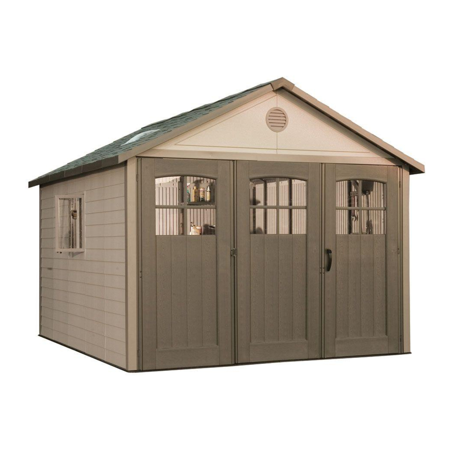
- Page 1 OUTDOOR STORAGE MODEL N° 6417 OWNER’S MANUAL Keep this Identification Number in case you need to contact our Customer Service Department.
- Page 2 Plan to spend a good part of your weekend putting together your fi ne Outdoor Storage Shed. Our Lifetime© Outdoor Storage Shed will surely last a long, long time, if you are patient, and take all the time necessary to put it together as we have instructed.
- Page 3 Lifetime continues to develop innovative products that outfi t the way you live. Lifetime makes the things you need for the lifestyle you want. By innovating products in and around the home, Lifetime simplifi es your everyday life and enables you to get the most out of your free time.
- Page 4 REGISTER YOUR LIFETIME PRODUCT TODAY! There are benefi ts to registering your Lifetime product. With our new online product registration form, it’s fast and easy! Register with us at www.lifetime.com and enjoy these great benefi ts: promotions! But you will need to provide a sales receipt to verify your product purchase date before warranty service will be provided.
- Page 5 BEFORE BEGINNING ASSEMBLY Keep the hardware bags and their contents separate. If any parts are missing, call our Customer Service Department. Identify and inventory all parts and hardware using the parts and hardware lists and identifi ers in this document. *Two adults required to complete assembly* Only adults should set up the product.
- Page 6 ASSEMBLY GUIDES Refer to the following areas throughout the instructions to assist in the assembly process: This area is located at the top, left-hand TOOLS AND HARDWARE REQUIRED FOR THIS PAGE corner of the page and indicates which tools and hardware are needed to complete the assembly steps on a page.
- Page 7 IMPORTANT NOTICES Level Surface Notice: Surface must be leveled before installation. We recommend building a level work space with a concrete or patio style surface. If the surface is not properly leveled, the Outdoor Shed will not assemble correctly. Proper surface leveling will save you time in the long run, so please do not ignore this step. Building Code Notice: Consult all local building codes, as well as city and county ordinances, to ensure that the construction of the Outdoor Shed does not require a building permit.
-
Page 8: Table Of Contents
PARTS & HARDWARE LIST BOX 1 Description BNH GABLE BRACE & ROOF INSTALLATION HARDWARE Description 1/4” x 5/8” Pan-Head Screw BOX 3 Door Brace Roof Panel for Skylight BNM METAL PARTS KIT 1 Window Wall Panel Left Hinge Assembly Wall Panel Center Hinge Assembly BNN METAL PARTS KIT 2 Roof Support Strip... - Page 9 PARTS & HARDWARE LIST (CONT.) Description Description BNA GABLE ASSEMBLY HARDWARE (x2) BNE DOOR FRAME & DOOR INSTALLATION HARDWARE Vent Screen 1/4” Cap Nut 1/4” x 5/8” Pan-Head Screw 1/4” Flat Washer BMZ GABLE INSTALLATION HARDWARE BMX WALL INSTALLATION HARDWARE 1/4”...
-
Page 10: Door Brace
PARTS & HARDWARE IDENTIFIER BOX 1 Parts shown at 8% of actual size Rear View Rear View Outer Roof Panel A Outer Roof Panel B Outer Floor Panel A Outer Floor Panel B 1/4” BLG (x1) AFB (x8) Extended Door Brace Door Brace Part shown at 15% of actual size Part shown at 4% of actual... -
Page 11: Left Hinge Assembly
PARTS & HARDWARE IDENTIFIER BOX 1 (CONT.) METAL PARTS KIT 1 [BNM] Parts shown at 8% of actual size 13/16” BKZ (x1) Center Hinge Assembly Bottom 1/4” BMG (x1) Right Hinge Assembly Bottom 1/4” BLK (x1) Left Hinge Assembly METAL PARTS KIT 2 [BNN] Parts shown at 8% of actual size 1/2”... -
Page 12: Box 2
PARTS & HARDWARE IDENTIFIER BOX 1 (CONT.) Parts shown at 8% of actual size 13/16” Extended Door End Channel BLM (x1) ” 13” Truss Support Strip 1/4” BLL (x1) 59.119” BLN (x1) BOX 2 Parts shown at 4% of actual size AHB (x1) Roof Panel for Skylight Wall Panel... -
Page 13: Roof Support Strip
PARTS & HARDWARE IDENTIFIER Parts shown at 8% of actual size BOX 2 Parts shown at 4% of actual size AGB (x1) Domed Skylight Window Center Roof Panel ” AFL (x14) Roof Support Strip Window Frame Center Roof Cap METAL PARTS KIT 1 [BNL] Parts shown at 8% of actual size 11/16”... -
Page 14: Adz 1/4" X 5/8" Pan-Head Screw
PARTS & HARDWARE IDENTIFIER BOX 2 (CONT.) HARDWARE BOX [BNJ] TRUSS FRAME & WALL SUPPORT INSTALLATION HARDWARE [BNI] Hardware shown at actual size (*Unless otherwise noted) ADZ (x110) 1/4” x 5/8” Pan-Head Screw 1/4” Cap Nut ACD (x4) ADK (x4) AHT (x8)* Floor Bracket TRUSS FRAME ASSEMBLY HARDWARE [BGV] (x4) -
Page 15: Box 3
PARTS & HARDWARE IDENTIFIER BOX 3 Parts shown at 4% of actual size AGQ (x1) AHB (x1) Center Roof Panel Roof Panel for Skylight AHD (x1) AHH (x1) Wall Panel Window Wall Panel Inner Floor Panel Parts shown at 8% of actual size AGB (x1) Domed Skylight Window... -
Page 16: 1/4" X 5/8" Pan-Head Screw
PARTS & HARDWARE IDENTIFIER BOX 3 (CONT.) METAL PARTS KIT 1 [BNG] Parts shown at 8% of actual size 11/16” 79 1/2” AFG (x1) Roof Truss Brace METAL PARTS KIT 2 [BNF] Part shown at 8% of actual size 1/2” Wall Support Channel ”... -
Page 17: Window Hinge
PARTS & HARDWARE IDENTIFIER BOX 3 (CONT.) WINDOW ASSEMBLY & INSTALLATION HARDWARE [BGU] (x2) (CONT.) AIR (x4) Window Hinge Sliding Window Stay Mounted Window Stay Parts shown at 50% of actual size AIT (x4) AIU (x4) Window Stay Window Latch Window Latch Bearing Bracket DOMED SKYLIGHT ASSEMBLY HARDWARE BAG [BEC] (x2) -
Page 18: 14" Shelf Bracket
PARTS & HARDWARE IDENTIFIER BOX 4 (CONT.) PARTS & HARDWARE BOX [BNO] Parts shown at 15% of actual size AIZ (x4) Pegboard Strip 14” Shelf Bracket Roof Cap Cover PEGBOARD STRIP INSTALLATION HARDWARE [BHC] Hardware shown at actual size TOOL CLIP ASSORTMENT [BHD] Parts shown at 50% of actual size ADW (x10) AIF (x1) - Page 19 PARTS & HARDWARE IDENTIFIER BOX 4 (CONT.) GABLE INSTALLATION HARDWARE [BMZ] Hardware shown at actual size 1/4” x 5/8” Pan-Head Screw WALL INSTALLATION HARDWARE [BMX] Hardware shown at actual size ADZ (x116) ADC (x1) 1/4” x 5/8” Pan-Head Screw 14” SHELF INSTALLATION HARDWARE [BMY] (x2) Hardware shown at actual size AEE (x4) ADX (x4)
- Page 20 PARTS & HARDWARE IDENTIFIER BOX 4 (CONT.) CENTER DOOR HARDWARE [BMV] Hardware shown at actual size AEE (x1) 1/4” Cap Nut ADZ (x9) End Plug 1/4” x 5/8” Pan-Head Screw 1/4” x 1 1/4” Carriage Bolt Hardware shown at 50% of Hardware shown at 15% of actual size actual size...
- Page 21 PARTS & HARDWARE IDENTIFIER BOX 4 (CONT.) RIGHT DOOR HARDWARE [BMU] (CONT.) Hardware shown at 15% of actual size Hardware shown at 50% of actual size AIK (x1) AHW (x1) Right Door Handle Thumb Lever Extension TRIM INSTALLATION HARDWARE [BND] Hardware shown at actual size ACK (x4) BMH (x10)
- Page 22 PARTS & HARDWARE IDENTIFIER BOX 4 (CONT.) DOOR FRAME & DOOR INSTALLATION HARDWARE [BNE] (CONT.) Hardware shown at 50% of actual size BBN (x1) Door Frame Support Bracket Carriage Latch DOOR WINDOW INSTALLATION HARDWARE [BNC] Hardware shown at actual size 1/4”...
- Page 23 TOOLS AND HARDWARE REQUIRED FOR THIS PAGE Concrete (1 cu. yd.) SITE PREPARATION - CONCRETE PLATFORM PREPARATION The actual dimensions of your shed (at its widest and longest points) are 11’ x 11’. Be sure to select a site that will accommodate these measurements.
- Page 24 TOOLS AND HARDWARE REQUIRED FOR THIS PAGE 2” x 4” x 123 1/2” 2” x 4” x 120 1/2” (x9) 16d 3” Common Nail ALTERNATIVE SITE PREPARATION: OPTION 1 - WOOD PLATFORM ASSEMBLY Ensure you use lumber that is treated and approved for outdoor outside dimensions.
- Page 25 TOOLS AND HARDWARE REQUIRED FOR THIS PAGE 27 1/2” x 96” x 3/4” Treated Plywood 8d 1 1/2” Common Nail 48” x 96” x 3/4” Treated Plywood 27 1/2” x 27 1/2” x 3/4” Treated Plywood (x1) ALTERNATIVE SITE PREPARATION: OPTION 1 - WOOD PLATFORM ASSEMBLY (CONT) Square up the frame by measuring from corner to corner.
- Page 26 TOOLS AND HARDWARE REQUIRED FOR THIS PAGE 2” x 4” x 123 1/2” 2” x 6” x 117” L-Bracket (x4) 8d 1 1/2” Common Nail (x16) Pea Gravel ALTERNATIVE SITE PREPARATION: OPTION 2 - FILLED WOOD FRAME ASSEMBLY Ensure frame is level. Square up the frame by measuring from corner to corner. Measurement A should equal Measurement B.
- Page 27 FLOOR ASSEMBLY PLASTIC PARTS REQUIRED LOCATED IN BOXES: 1, 2, 3 Parts shown at 4% of actual size Outer Floor Panel A AGJ (x6) Inner Floor Panel Outer Floor Panel B TOOLS REQUIRED Safety Glasses...
- Page 28 TOOLS AND HARDWARE REQUIRED FOR THIS PAGE NO HARDWARE REQUIRED FOR THIS PAGE FLOOR PANEL ASSEMBLY Hold one (1) Outer Floor Panel “B” (AGT) at an angle against one (1) Outer Floor Panel “A” (AGS) so the tabs on Panel CAUTION Sharp objects may damage your fl...
- Page 29 TOOLS AND HARDWARE REQUIRED FOR THIS PAGE NO HARDWARE REQUIRED FOR THIS PAGE Hold an Inner Floor Panel (AGJ) at an angle against another Inner Floor Panel so the tabs on each Panel fi t underneath the other Panel. Then, lay the Panel fl at. Connect the Inner Floor Panels to the Outer Floor Panels using the same procedure.
- Page 30 TOOLS AND HARDWARE REQUIRED FOR THIS PAGE NO HARDWARE REQUIRED FOR THIS PAGE Repeat the previous step to connect all the Inner Floor Panels (AGJ) to each other. Finally, connect the last two Outer Floor Panels (AGS & AGT) to the Inner Floor Panels.
- Page 31 TRUSS & WALL CHANNEL ASSEMBLY HARDWARE BOX REQUIRED: BGV (x4) HARDWARE REQUIRED Hardware shown at actual size Hardware shown at 50% of actual size AAK (x40) ADJ (x40) 1/4” Cap Nut AHT (x8) Floor Bracket AIP (x4) METAL PARTS REQUIRED METAL PARTS KITS REQUIRED: BNN, BNF, BNG, BNL, BNK Parts shown at 8% of actual size 11/16”...
- Page 32 TOOLS AND HARDWARE REQUIRED FOR THIS PAGE 7/16” AAK (x6) AIP (x1) ADJ (x6) (Not to scale) TRUSS ASSEMBLY Fit two Truss Support Strips (AFP) together. Bolt Truss Support Strips, Truss Gutter Connector (AIP), and two Truss Gutter Channels (AFH) as shown using the required hardware. WARNING Do not overtighten the Cap Nut.
- Page 33 TOOLS AND HARDWARE REQUIRED FOR THIS PAGE 7/16” AAK (x4) (Not to scale) ADJ (x4) Attach Truss Assembly to two Wall Support Channels (AFQ) using 1/4” x 1 1/2” Hex Bolts (AAK) and 1/4” Cap Nuts (ADJ). Do not completely tighten the Cap Nut until after Truss is secured to the Wall. WARNING Do not overtighten the Cap Nut.
- Page 34 WALL PANEL INSTALLATION HARDWARE REQUIRED HARDWARE BAG REQUIRED: BMX Hardware shown at actual size ADZ (x78) ADC (x1) 1/4” x 5/8” Pan-Head Screw METAL PARTS REQUIRED METAL PARTS KIT REQUIRED: BNN Part shown at 8% of actual size 1/2” Corner Channel PLASTIC PARTS REQUIRED LOCATED IN BOXES: 2, 3, 4 Part shown at 4% of actual size...
- Page 35 TOOLS AND HARDWARE REQUIRED FOR THIS PAGE ADZ (x18) WALL ASSEMBLY Lock a Wall Panel (AHD) into the right front corner position by inserting the tabs at the bottom of the Wall Panel into the slots on the Shed Floor. After inserting the tabs, slide the Wall Panel to the right to lock it in place. Install a Window Wall Panel (AHH) and secure with six (6) 1/4”...
- Page 36 TOOLS AND HARDWARE REQUIRED FOR THIS PAGE Install next Wall Panel (AHD) at the right, rear corner of the Shed. Align the holes in a Corner Channel (AFR) with the holes in two corner Wall Panels and secure the Corner Channel 1/4”...
- Page 37 TOOLS AND HARDWARE REQUIRED FOR THIS PAGE ADZ (x18) Assemble next three Wall Panels (AHD). Secure the Wall Panels together with eighteen (18) 1/4” x 5/8” Phillips Pan- Head Screws (ADZ). Note: A second adult should apply pressure to the opposite side of the wall for easy insertion of screws.
- Page 38 TOOLS AND HARDWARE REQUIRED FOR THIS PAGE Install the next Wall Panel at the left, rear corner of the Shed and connect the two rear, corner Wall Panels (AHD) 1/4” x 5/8” Phillips Pan-Head Screws (ADZ). Connect the next Wall Panel using six (6) 1/4”...
- Page 39 TRUSS FRAME & WALL SUPPORT INSTALLATION HARDWARE BAG REQUIRED: BNI HARDWARE REQUIRED Hardware shown at actual size (*Unless otherwise noted) AAK (x18) ADJ (x18) AHT (x6)* 1/4” Cap Nut ADZ (x96) (Not all are used) Floor Bracket (Not all are used) 1/4”...
- Page 40 TOOLS AND HARDWARE REQUIRED FOR THIS PAGE 3/8” ADZ (x64) ACD (x4) ADK (x4) TRUSS INSTALLATION Starting at the back of the Shed, secure a Truss Frame Assembly to the center of each Left and Right Wall Panel with the 1/4” x 5/8” Pan-Head Screws (ADZ). DO NOT use the 1/4” x 5/8” Pan-Head Screws (ADZ) to secure the Truss Frame Assembly to the center divider in the Window Wall Panel.
- Page 41 TOOLS AND HARDWARE REQUIRED FOR THIS PAGE 7/16” ADJ (x8) AAK (x8) REAR GABLE SUPPORT INSTALLATION Attach a Short Vertical Extension Channel (AFN) to Attach a Long Vertical Extension Channel (AFJ) to a a Wall Support Channel. Ensure Extension Wall Support Channel (AFQ). Repeat. Channel is installed in the correct direction.
- Page 42 GABLE ASSEMBLY HARDWARE REQUIRED HARDWARE BAG REQUIRED: BNA (x2) Hardware shown at actual size ADZ (x8) AEE (x10) ADW (x10) 1/4” x 5/8” Pan-Head Screw Parts shown at 15% of actual size Louvered Vent Vent Screen PLASTIC PARTS REQUIRED LOCATED IN BOX: 1 Parts shown at 4% of actual size TOOLS REQUIRED Safety Glasses...
- Page 43 TOOLS AND HARDWARE REQUIRED FOR THIS PAGE ADZ (x8) GABLE ASSEMBLY Set the edge of Gable Half 2 (AGI) over the edge of Gable Half 1 (AGH) as shown. 1/4” x 5/8” Pan-Head Screws (ADZ).
- Page 44 TOOLS AND HARDWARE REQUIRED FOR THIS PAGE ADW (x10) AEE (x10) Attach the Louvered Vent (AGP) and Vent Screen (AIQ) Assembly using fi ve (5) #10 x 1/2” Flat Washers (AEE) and fi ve (5) #10 x 3/4” Phillips Pan-Head Screws (ADW) Repeat this section for the second Gable.
- Page 45 LEFT DOOR ASSEMBLY HARDWARE BAG REQUIRED: BMW HARDWARE REQUIRED Hardware shown at actual size Dead Bolt Latch 1/4” Cap Nut ADZ (x9) 1/4” x 5/8” Pan-Head Screw 1/4” Flat Washer METAL PARTS REQUIRED LOCATED IN BOX 1 AND METAL PARTS KIT: BNM Part shown at 8% of actual size 13/16”...
- Page 46 TOOLS AND HARDWARE REQUIRED FOR THIS PAGE AHM (x1) ADZ (x9) (Not to scale) LEFT DOOR ASSEMBLY Door Braces (AFB) to the inside of the Left Door (AGO) using the required hardware. Place a Dead Bolt Latch (AHM) in the notch at the top of the door as shown. Orient a Center Hinge Assembly (BKZ) as shown, and slide the Center Hinge Assembly down over the bottom lip of the Dead Bolt Latch and the end of the Left Door.
- Page 47 TOOLS AND HARDWARE REQUIRED FOR THIS PAGE 7/16” AHM (x1) (Not to scale) Place a second Dead Bolt Latch (AHM) in the notch at the bottom of the Left Door, and continue sliding the Center Hinge Assembly (BKZ) over the Left Door and over bottom lip of the second Dead Bolt Latch. Note: Ensure the Center Hinge Assembly (BKZ) is oriented as shown.
- Page 48 CENTER DOOR ASSEMBLY HARDWARE BAG REQUIRED: BMV HARDWARE REQUIRED Hardware shown at actual size Hardware shown at 15% of actual size AEE (x1) AHZ (x1) Center Door Handle ADZ (x9) 1/4” x 5/8” Pan-Head Screw actual size AIA (x1) Center Door Lock Bracket End Plug AIB (x1)
- Page 49 TOOLS AND HARDWARE REQUIRED FOR THIS PAGE ADZ (x9) CENTER DOOR ASSEMBLY Insert an End Plug (BBH) into each end of the Extended Door Brace (BLG), as shown. Door Braces (AFB) and the Extended Door Brace (BLG) to the inside of the Center Door (AGZ), as shown, using the required hardware.
- Page 50 TOOLS AND HARDWARE REQUIRED FOR THIS PAGE AHZ (x1) (Not to scale) BBI (x1) (Not to scale) AHM (x1) (Not to scale) AEE (x1) Connect the Center Door Handle (AHZ) and the Inside Center Door Handle (BBI) to the Center Door using the hardware shown.
- Page 51 TOOLS AND HARDWARE REQUIRED FOR THIS PAGE 7/16” AIB (x1) (Not to scale) AIA (x1) (Not to scale) Orient the Extended Strike Plate (AIB) and slide it over the holes in the Extended Door End Channel, as shown. Secure the Extended Strike Plate, Extended Door End Channel, and Center Door Lock Bracket (AIA) to the Center Door using the required hardware.
- Page 52 TOOLS AND HARDWARE REQUIRED FOR THIS PAGE Align the holes in the Extended Door Brace with those in the Extended Door End Channel, and secure using the required hardware.
- Page 53 RIGHT DOOR ASSEMBLY HARDWARE BAG REQUIRED: BMU HARDWARE REQUIRED Hardware shown at actual size Hardware shown at 15% of actual size actual size AHV (x1) Extended Door Latch 1/4” Cap Nut AIK (x1) AIL (x1) Right Door Handle Right Door Lock Bracket Hardware shown at 50% of actual size...
- Page 54 TOOLS AND HARDWARE REQUIRED FOR THIS PAGE ADZ (x9) RIGHT DOOR ASSEMBLY Door Braces (AFB) to the inside of the Right Door (AGZ) using the required hardware. Slide a Extended Door End Channel (BLH) down over the edge of the Right Door as shown.
- Page 55 TOOLS AND HARDWARE REQUIRED FOR THIS PAGE AHZ (x1) (Not to scale) AIO (x1) (Not to scale) Slide the nubs of the Thumb Lever (AIO) down the slots and into the holes of the Right Door Handle (AIK). Hole Slots Insert the end of the Thumb Lever through the slot in the Right Door and connect the Door Handle Assembly to the Right Door using the hardware shown.
- Page 56 TOOLS AND HARDWARE REQUIRED FOR THIS PAGE 7/16” AHV (x1) (Not to scale) AIL (x1) (Not to scale) AHX (x1) (Not to scale) Align the holes in the center of the Extended Door End Channel with the notch in the edge of the Right Door. Connect the Right Door Lock Bracket (AIL), Extended Door Latch (AHV), and Latch Cover Plate (AHX) to the Right Door as shown using the required hardware.
- Page 57 TOOLS AND HARDWARE REQUIRED FOR THIS PAGE ADW (x1) AHY (x1) AHW (x1) (Not to scale) Connect the Thumb Lever Extension (AHW) to the Thumb Lever with one (1) #10 x 3/4” Phillips Pan-Head Screw (ADW). Note: The lip of the Thumb Lever Extension (AHW) fi ts under the Thumb Lever . Connect the Latch Spring (AHY) to the Extended Door Latch (AHV) and Latch Cover Plate (AHX).
- Page 58 DOOR FRAME AND DOOR INSTALLATION HARDWARE REQUIRED HARDWARE BAG REQUIRED: BNE Hardware shown at actual size BBL (x6) BBM (x4) ABU (x6) 1/4” x 5/8” Pan-Head Screw AEB (x8) BBG (x1) 1/4” Flat Washer 5/16” Jam Nut AID (x1) L-Key with Phillips Head ACA (x4) ADJ (x16) 1/4”...
- Page 59 METAL PARTS REQUIRED LOCATED IN BOX 1 AND METAL PARTS KIT: BNM, BNN Parts shown at 8% of actual size Bottom 1/4” BLK (x1) Left Hinge Assembly 1/4” BLL (x1) 13” BLM (x1) 59.119” BLN (x1) Part shown at 15% of actual size Corner Frame Bracket HARDWARE BAG REQUIRED: BNE TOOLS REQUIRED...
- Page 60 TOOLS AND HARDWARE REQUIRED FOR THIS PAGE NO HARDWARE REQUIRED FOR THIS PAGE Ensure you use the correct Hinge Assembly for the Left and Right Doors. The hinge faces outward on each 10.1 door, and the head of the hinge pin always goes on top. Hinge faces outward and head Hinge faces outward and head of hinge pin goes on top.
- Page 61 TOOLS AND HARDWARE REQUIRED FOR THIS PAGE NO HARDWARE REQUIRED FOR THIS PAGE LEFT DOOR ASSEMBLY Slide the Left Door Assembly down through the channel of a Left Hinge Assembly (BLK) as shown. 10.2 Rear side of Left Door...
- Page 62 TOOLS AND HARDWARE REQUIRED FOR THIS PAGE 7/16” Align the holes in the Left Hinge Assembly with the notch in the Left Door, and secure the Left Hinge Assembly 10.3 to the Left Door using the required hardware. Slide a Corner Door Frame (BLJ) into the Left Hinge Assembly, and align the holes, as shown. 10.4...
- Page 63 TOOLS AND HARDWARE REQUIRED FOR THIS PAGE 7/16” AEB (x1) Secure a Corner Frame Bracket (BLI) to the Corner Door Frame and Left Hinge Assembly using the required 10.5 hardware. CENTER DOOR ASSEMBLY Slide the Center Door Assembly down through the channel of the Door Hinge End Channel, as shown. 10.6...
- Page 64 TOOLS AND HARDWARE REQUIRED FOR THIS PAGE 7/16” RIGHT DOOR ASSEMBLY Orient the Right Hinge Assembly (BMG), as shown. Slide the Hinge Frame down over the right side of the Right Door 10.7 (AGZ), as shown. Rear side of Right Door Align the holes in the Right Hinge Assembly with the notch in the Right Door, and secure the Right Hinge 10.8 Assembly to the Right Door using the required hardware.
- Page 65 TOOLS AND HARDWARE REQUIRED FOR THIS PAGE 7/16” AEB (x1) Slide the Right Hinge Assembly over a Corner Door Frame (BLJ) and align the holes, as shown. 10.9 Secure a Corner Frame Bracket (BLI) to the Corner Door Frame and Right Hinge Assembly using the required 10.10 hardware.
- Page 66 TOOLS AND HARDWARE REQUIRED FOR THIS PAGE 7/16” ACA (x4) ADJ (x4) Slide the Long Glider Track (BLL) next to the Short Glider Track (BLM). 10.11 Align the square holes in the two Tracks with the square holes in Glider Track Extension (BLN) and connect the 10.12 three pieces using the required hardware.
- Page 67 TOOLS AND HARDWARE REQUIRED FOR THIS PAGE 7/16” BBM (x4) 10.13 over the Left and Center Doors. Connect the right side of the Top Door Frame Assembly to the right Corner Bracket using the required 10.14 hardware. Connect the left side of the Top Door Frame Assembly and the Carriage Latch (BBN) to the left Corner Frame Bracket using the required hardware.
- Page 68 TOOLS AND HARDWARE REQUIRED FOR THIS PAGE 7/16” AID (x1) (Not to scale) (Not to scale) Connect both Carriage Wheels (BBE) to the Carriage Bracket (BBK) to form the Carriage Assembly using the required 10.15 hardware. Do not overtighten. Place the Carriage Wheels into the Header Frame Track Assembly. 10.16...
- Page 69 TOOLS AND HARDWARE REQUIRED FOR THIS PAGE 5/16” BBG (x1) ADJ (x4) ACA (x4) (Not to scale) Connect the Carriage Bracket to the Extended Door Brace using one (1) 5/16” x 2 1/2” Hex Bolt (BBG) 5/16” 10.17 Jam Nuts (AAV). Place one (1) Jam Nut above the Carriage Bracket and one (1) below. Note: You may need to adjust the Nuts (AAV) later on to allow the door to open freely.
- Page 70 TOOLS AND HARDWARE REQUIRED FOR THIS PAGE ADZ (x5) AT LEAST TWO ADULTS REQUIRED FOR STEPS ON THIS PAGE Place the bottom of the Door/Frame Assembly next to the front Floor Panels of the shed, and lift the Door/ 10.19 Frame Assembly up in place.
- Page 71 TOOLS AND HARDWARE REQUIRED FOR THIS PAGE 7/16” ADZ (x6) AT LEAST TWO ADULTS REQUIRED FOR THIS STEP There are two columns of holes along the Corner Frames. Align the column of six (6) holes (Column 1) in the 10.21 left Corner Frame with those near the end of the Wall Panel.
- Page 72 TOOLS AND HARDWARE REQUIRED FOR THIS PAGE ADX (x4) BBJ (x1) Dead Bolt Strike Plates (AHL) in the indentations on the Floor Panels at the locations shown. 10.23 #10 x 1/2” Pan-Head Screws (ADX). Finally, secure the 4” Floor Strike Plate (BBJ) 1/4”...
- Page 73 CORNER TRIM INSTALLATION HARDWARE BAG REQUIRED: BND HARDWARE REQUIRED Hardware shown at actual size ACK (x4) BMH (x10) Black, Plastic Corner Trim Bracket Metal Corner Trim Bracket PLASTIC PARTS REQUIRED LOCATED IN BOX: 4 Part shown at 8% of actual size 13/16”...
- Page 74 TOOLS AND HARDWARE REQUIRED FOR THIS PAGE ADX (x10) FRONT CORNER TRIM INSTALLATION Using the required hardware, connect five (5) Metal Corner Trim Brackets (BMH) to the front corners of your Shed, 11.1 11.1 as shown. 11.2 Slide a Corner Trim (AQX) over the Metal Corner Trim Brackets, as shown. 11.2 11.1...
- Page 75 TOOLS AND HARDWARE REQUIRED FOR THIS PAGE Align the top of the Corner Trim with the top of the Wall Wall Panel and fasten with a #8 x 1” Phillips Pan-Head 11.3 Screw (ACK). Insert the Screw on the side of the Shed to hide it under the eaves. Repeat steps 11.1 - 11.3 for the second Front Corner Trim.
- Page 76 TOOLS AND HARDWARE REQUIRED FOR THIS PAGE REAR CORNER TRIM INSTALLATION Snap six (6) Plastic Corner Trim Brackets (AGA) #10 x 11.4 11.4 11.1 1/2” Phillips Pan-Head Screws (ADX). Note: The tab on the Trim Brackets fit into the six screw indentations along each corner of the Shed. 11.2 11.5 Slide a Corner Trim (AQX) onto the Plastic Corner Trim Brackets.
- Page 77 DOMED SKYLIGHT ASSEMBLY HARDWARE REQUIRED HARDWARE BAG REQUIRED: BEC Hardware shown at actual size (*Unless noted otherwise) *AHI Butyl Tape LOCATED IN BOXES: 2, 3 PLASTIC PARTS REQUIRED Part shown at 8% of actual size Part shown at 4% of actual size Domed Skylight Roof Panel for Domed Skylight TOOLS REQUIRED...
- Page 78 TOOLS AND HARDWARE REQUIRED FOR THIS PAGE (Not to scale) DOMED SKYLIGHT ASSEMBLY Use a plain screwdriver to gently remove any excess plastic from the twelve holes in the Roof Panel for Domed 12.1 Skylight (AHB). It’s important that the hole stay square; try not to round the corners of the edges of the holes. Stick the end of the Butyl Tape (AHI) over the groove and top, left hole of the Roof Panel for Domed Skylight as indicated below.
- Page 79 TOOLS AND HARDWARE REQUIRED FOR THIS PAGE 3/8” Insert one (1) #10 x 5/8” Carriage Bolt (ACR) through each hole in the Domed Skylight. Press the Bolt through the 12.3 Butyl Tape and through the Roof Panel for Domed Skylight. Exterior View Secure the Domed Skylight to the Roof Panel with one (1) #10 Flat Washer (AEE) and one (1) #10 Cap Nut (ADK) for 12.4...
- Page 80 GABLE INSTALLATION HARDWARE REQUIRED HARDWARE BAG REQUIRED: BMZ Hardware shown at actual size 1/4” x 5/8” Phillips Pan-Head Screw PLASTIC PARTS REQUIRED FROM SECTION: 6 Parts shown at 4% of actual size LOCATED IN BOX: 5 (Assembled earlier) (Assembled earlier) TOOLS REQUIRED Phillips Screwdriver Safety Glasses...
- Page 81 TOOLS AND HARDWARE REQUIRED FOR THIS PAGE REAR GABLE INSTALLATION 1/4” x 5/8” Phillips 13.1 Pan-Head Screws (ADZ). Note: Tighten the Screws on the Vertical Extension Channels after the Gable is installed. FRONT GABLE INSTALLATION 1/4” x 5/8” Phillips Pan-Head Screws (ADZ) at the locations shown.
- Page 82 GABLE BRACE & ROOF INSTALLATION HARDWARE REQUIRED HARDWARE BAG REQUIRED: BNH Hardware shown at actual size (*Unless otherwise noted) ADZ (x185) 1/4” x 5/8” Pan-Head Screw ADK (x1) ADX (4) (Not all are used) LOCATED IN BOXES 1, 2, 3 METAL PARTS REQUIRED Parts shown at 8% of actual size 7/16”...
- Page 83 TOOLS AND HARDWARE REQUIRED FOR THIS PAGE ADK (x1) ACF (x1) ADX (x4) GABLE BRACE INSTALLATION Install the Gable Truss Brace (AFF) 1/4” x 1 14.1 1/2” Hex Bolts (AAK) and the 1/4” NKE Cap Nuts (ADJ) from the bottom of the Truss Assembly, and then reattach to the #10 x 1/2”...
- Page 84 TOOLS AND HARDWARE REQUIRED FOR THIS PAGE ROOF ASSEMBLY Install Outer Roof Panels A & B (AGU & AGV) at the front of the Shed. Always start inserting the 1/4” x 5/8” Phillips Pan- 14.2 Head Screws (ADZ) at the top of the Roof Panel. Note: This is an interior upward view.
- Page 85 TOOLS AND HARDWARE REQUIRED FOR THIS PAGE Inner Roof Panels (AGQ) and four (4) Roof Support Strips (AFL) to the Shed as shown. Roof Panels for 14.3 Skylights (AHB) can be inserted into any of the center Roof Panel sections. Note: This section applies to the two types of Roof Panels: Inner Roof Panel (AGQ) and Roof Panel for Domed Skylight (AHB).
- Page 86 TOOLS AND HARDWARE REQUIRED FOR THIS PAGE Roof Panels for Skylights (AHB) and six (6) Roof Support Strips (AFL) using the required hardware. 14.4 Position the Outer Roof Panel A (AGU) Outer Roof Panel B (AGV). 14.5 Note: Only use a hand screwdriver on this step.
- Page 87 TOOLS AND HARDWARE REQUIRED FOR THIS PAGE Connect the End Roof Caps (AGE) and Center Roof Caps (AFY) 14.6...
- Page 88 TOOLS AND HARDWARE REQUIRED FOR THIS PAGE Install a Roof Cap Cover (AHA) 1/4” x 5/8” Phillips Pan-Head Screws (ADZ) 14.7 for each Roof Cap Cover. Along the outside edges of the Shed, fasten the Channels to the underside of the Roof Panels (Fig. 1). Insert 14.8 two Foam Cubes (AJA) CAUTION...
- Page 89 WINDOW ASSEMBLY & INSTALLATION HARDWARE REQUIRED HARDWARE BAG REQUIRED: BGU (x2) Hardware shown at actual size ADX (x44) AEE (x4) ADZ (x8) ADW (x8) 1/4” x 5/8” Pan-Head Screw ACD (x4) ADK (x4) ACB (x8) ACF (x4) AIE (x4) AIN (x4) AIV (x4) AIR (x8) Mounted Window Stay...
- Page 90 TOOLS AND HARDWARE REQUIRED FOR THIS PAGE AIR (x4) (Not to scale) Slide Window Hinge Tubes (AIR) into the upper and lower hinge holes and fi t a Window Frame (AHG) over the Hinge 15.1 Tubes.
- Page 91 TOOLS AND HARDWARE REQUIRED FOR THIS PAGE Place a Window (AHF) onto the Window Frame. Fasten the Window to the Frame with #10 x 1/2” Pan Head Screws 15.2 (ADX) in the locations shown. Note: Remove plastic fi lm from both sides of window before installing. Note: Insert Screws into the holes with circles.
- Page 92 TOOLS AND HARDWARE REQUIRED FOR THIS PAGE ADZ (x4) (Not to scale) ADW (x4) (Not to scale) Attach Window Stay Brackets (AIV) to the inside of the Window Wall Panel (AHH). 15.3 Attach a Mounted Window Stay (AIE) to the bottom of the Window Frame. 15.4...
- Page 93 TOOLS AND HARDWARE REQUIRED FOR THIS PAGE (Not to scale) Fit a Sliding Window Stay (AIN) into the Mounted Window Stay. To add rigidity to the nub of the Sliding Window 15.5 Stays, insert #10 x 1/2” Pan-Head Screws (ADX) as shown. Attach a Sliding Window Stay (AIN) to the Window Stay Bracket (AIV) using the required hardware.
- Page 94 TOOLS AND HARDWARE REQUIRED FOR THIS PAGE ACB (x4) AIT (x4) (Not to scale) AIU (x4) (Not to scale) Fit a Window Latch Bearing (AIU) into a Window Latch (AIT). Attach the Window Latch to the upper latch location with a 15.7 #10 x 1 1/4”...
- Page 95 DOOR WINDOW INSTALLATION HARDWARE BAG REQUIRED: BNG HARDWARE REQUIRED Hardware shown at actual size 1/4” x 5/8” Pan-Head Screw LOCATED IN BOX: 5 PLASTIC PARTS REQUIRED Parts shown at 4% of actual size Door Window TOOLS REQUIRED Phillips Screwdriver Safety Glasses...
- Page 96 TOOLS AND HARDWARE REQUIRED FOR THIS PAGE DOOR WINDOW INSTALLATION Connect a Door Window (BLO) to each Door using the required hardware. 16.1...
- Page 97 ACCESSORY INSTALLATION HARDWARE REQUIRED HARDWARE BAGS REQUIRED: BMY, BHC, BHD Hardware shown at actual size Hardware shown at actual size ADW (x10) ADX (x8) AEE (x8) Hardware shown at 50% of actual size Toolholder AIF (x1) AIG (x1) 4” Double-Arm Hook L-Hook LOCATED IN PARTS &...
- Page 98 TOOLS AND HARDWARE REQUIRED FOR THIS PAGE ADX (x8) AEE (x8) 14” x 30” SHELF INSTALLATION Insert Shelf Brackets (AIZ) into notches in any Wall Support Channel. Place a 14” x 30” Shelf (AFT) on the Shelf 17.1 Brackets and secure with #10 Flat Washers (AEE) and #10 x 1/2” Pan-Head Screws (ADX). Repeat this step for the second Shelf.
- Page 99 TOOLS AND HARDWARE REQUIRED FOR THIS PAGE ADW (x10) (Not all screws are used) PEGBOARD STRIP INSTALLATION Using a Level, position the Pegboard Strip (AFU) in the desired location. Screw the Pegboard Strip to the Wall 17.3 using fi ve (5) #10 x 3/4” Phillips Pan-Head Screws (ADW). See Note. Note: The Pegboard Strip is screwed directly into the plastic.
- Page 100 FINAL STEPS HARDWARE REQUIRED HARDWARE BAG REQUIRED: BNH Hardware shown at actual size ADZ (x4) 1/4” x 5/8” Pan-Head Screw CHECK WITH YOUR LOCAL HARDWARE STORE FOR ANCHORING HARDWARE FOR YOUR PLATFORM TOOLS REQUIRED Safety Glasses 5/16” Wrench Phillips Screwdriver Hammer Drill 3/16”...
- Page 101 TOOLS AND HARDWARE REQUIRED FOR THIS PAGE 5/16” 3/16” ADZ (x4) CENTER & LEFT DOOR ADJUSTMENT 18.1 18.1 Hex Bolt on the Carriage Bracket to raise or lower the Center Door. Once the door has been adjusted to the desired height, retighten the Nuts. Carriage Bracket Adjust these nuts to raise and lower the Center Door.
- Page 102 CLEANING & CARE ® Congratulations on your Lifetime product purchase. By following the instructions below, your new Lifetime product should provide you with years of service and enjoyment. Cleaning and Care The polyethylene panels are stain- and solvent-resistant. Most stains can be removed, using a mild soap and a soft-bristled brush.
- Page 103 5. This product is not intended for institutional or commercial use; Lifetime Products, Inc. does not assume any liability for such use. Institutional or commercial use will void the warranty.
- Page 104 ® ENHANCE YOUR LIFETIME PURCHASE BY ADDING ACCESSORIES OR OTHER GREAT PRODUCTS To purchase accessories or other Lifetime Products, visit us at: www.lifetime.com Or call: 1-800-424-3865...
Need help?
Do you have a question about the 6417 and is the answer not in the manual?
Questions and answers