Table of Contents
Advertisement
Quick Links
Trace Oxygen Analyzer
OPERATING INSTRUCTIONS FOR
MODEL 3000ZA2G
Trace Oxygen Analyzer
P/N M86303
06/18/2013
DANGER
Toxic gases and or flammable liquids may be present in this monitoring system.
Personal protective equipment may be required when servicing this instrument.
Hazardous voltages exist on certain components internally which may persist
for a time even after the power is turned off and disconnected.
Only a trained service technician should open the front door of this instrument.
Only a trained service technician should conduct maintenance and/or
servicing. Before conducting any maintenance or servicing, consult with
authorized supervisor/manager.
Teledyne Analytical Instruments
i
Advertisement
Table of Contents

Related Manuals for Teledyne 3000ZA2G


Summary of Contents for Teledyne 3000ZA2G
- Page 1 Trace Oxygen Analyzer OPERATING INSTRUCTIONS FOR MODEL 3000ZA2G Trace Oxygen Analyzer P/N M86303 06/18/2013 DANGER Toxic gases and or flammable liquids may be present in this monitoring system. Personal protective equipment may be required when servicing this instrument. Hazardous voltages exist on certain components internally which may persist for a time even after the power is turned off and disconnected.
- Page 5 Teledyne Analytical Instruments, 16830 Chestnut Street, City of Industry, CA 91748.
- Page 6 The internal valves are entirely under the control of the 3000ZA2G electronics and can be used to automatically switch between gases in synchronization with the analyzer’s operation.
- Page 7 3000ZA2G Important Notice Model 3000ZA2G complies with all of the requirements of the Commonwealth of Europe (CE) for Radio Frequency Interference, Electromagnetic Interference (RFI/EMI), and Low Voltage Directive (LVD). The following International Symbols are used throughout the Instruction Manual. These symbols are visual indicators of important and immediate warnings and when you must exercise CAUTION while operating the instrument.
-
Page 8: Safety Messages
Technician Symbol: All operations marked with this symbol are to be performed by qualified maintenance personnel only. NOTE: Additional information and comments regarding a specific component or procedure are highlighted in the form Symbol of a note. Teledyne Analytical Instruments... - Page 9 Manuals do get lost. Additional manuals can be obtained from Teledyne Analytical Instruments at the address given in the Appendix. Some of our manuals are available in electronic form via the internet. Please visit our website at: www.teledyne-ai.com.
- Page 10 Since the use of this instrument is beyond the control of Teledyne Analytical Instruments, no responsibility by Teledyne Analytical Instruments, its affiliates, and agents for damage or injury from misuse or neglect of this equipment is implied or assumed.
-
Page 11: Table Of Contents
3.3.1 Gas Connections 3.3.2 Calibration Gas 3.3.3 Electrical Connections 3.3.3.1 Primary Input Power 3.3.3.2 50-Pin Equipment Interface Connector 3.3.3.3 RS-232 Port 3.4 Testing the System Operation ............... 27 Teledyne Analytical Instruments viii... - Page 12 4.6.2 Fixed Range Analysis 4.7 The Analyze Function 4.8 Signal Output Maintenance ..............53 5.1 Routine Maintenance 5.2 Sensor Replacement 5.3 Fuse Replacement 5.4 System Self Diagnostic Test Teledyne Analytical Instruments...
- Page 13 3000ZA2G 5.5 Major Internal Components 5.6 Cleaning 5.7 Troubleshooting Appendix ............... 57 A-1 Specifications A-2 Recommended 2-Year Spare Parts List A-3 Drawing List Teledyne Analytical Instruments...
- Page 14 Trace Oxygen Analyzer List of Figures Figure 1-1: Model 3000ZA2G Front Panel Figure 1-2: Model 3000ZA2G Rear Panel Figure 2-1: Sensor Offset Voltage Figure 2-2: Zirconia Sensor Assembly Figure 2-3: Flow Diagram Figure 2-4: Component Locations ...
- Page 15 Table 3-3: Remote Calibration Connections Table 3-4: Range ID Relay Connections Table 3-5: Commands via RS-232 Input Table 3-6: Required RS-232 Options Table 5-1: Self-Test Result Display Table 5-2: Troubleshooting Teledyne Analytical Instruments...
-
Page 16: Introduction
(ppm) level to 25% oxygen in background gases consistent with the zirconium oxide sensor. This manual covers the Model 3000ZA2G 19” rack-mount units with CE mark. These units are for indoor use in a non-hazardous environment. -
Page 17: Front Panel
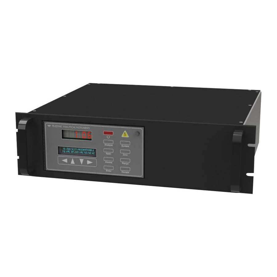
1.4 Front Panel The standard 3000ZA2G is housed in a rugged metal case designed for installation into a standard 19” equipment rack. All controls and displays are accessible from the front panel. See Figure 1-1. The front panel has thirteen buttons for operating the analyzer, a digital meter, an alphanumeric display, a flowmeter, and sample flow control valve. -
Page 18: Figure 1-1: Model 3000Za2G Front Panel
Trace Oxygen Analyzer Introduction Figure 1-1: Model 3000ZA2G Front Panel Function Keys: Six touch-sensitive membrane switches are used to change the specific function performed by the analyzer: Analyze Perform analysis for oxygen content of a sample gas. System Perform system-related tasks (described in detail ... - Page 19 The Standby turns off the display and outputs but circuitry is still operating. CAUTION: THE POWER ENTRY SWITCH ON THE REAR OF THE INSTRUMENT MUST BE TURNED OFF TO FULLY DISCONNECT POWER FROM THE INSTRUMENT. WHEN CHASSIS IS EXPOSED OR WHEN ACCESS Teledyne Analytical Instruments...
-
Page 20: Rear Panel (Equipment Interface)
Ventilation Module w/ Fuse RS-232 Port Housing 50-Pin Equipment Connector Auto Cal Valves Connections (optional) Figure 1-2: Model 3000ZA2G Rear Panel Power Connection Factory configured for either 115 VAC or 230 VAC operation , 50/60 Hz. Teledyne Analytical Instruments... - Page 21 Analog Outputs: 0–1 VDC oxygen concentration plus 0-1 VDC range ID Alarm Connections: 2 concentration alarms and 1 system alarm. Remote Valve: Used in the 3000ZA2G for controlling external solenoid valves only. Remote Span/Zero: Digital inputs allow external control of analyzer calibration.
-
Page 22: Operational Theory
THE SENSOR IS HOT. DO NOT TOUCH THE SENSOR OR ALLOW FLAMMABLE MATERIAL TO COME IN CONTACT WITH THE ASSEMBLY. THE SENSOR ASSEMBLY REMAINS HOT EVEN IN STANDBY MODE. REMOVE POWER FROM THE INSTRUMENT AND ALLOW SENSOR TO COOL FOR Teledyne Analytical Instruments... - Page 23 The sensor offset voltage changes with sample flowrate as shown in Figure 2-1. Assuming that the environment remains constant and within the specifications of the sensor, the difference in offset voltage between Teledyne Analytical Instruments...
-
Page 24: Figure 2-1: Sensor Offset Voltage
The non-linear output is linearized by the system software and a linear output signal is generated and used by the DAC circuit to produce the requisite output signals. Teledyne Analytical Instruments... -
Page 25: Sample System
Depending on the mode of operation either sample or calibration gas is delivered. The Model 3000ZA2G sample system is designed and fabricated to ensure that the oxygen concentration of the gas is not altered as it travels through the sample system. -
Page 26: Zirconium Oxide Sensor Application Notes
Use a moisture trap or filter to remove any water vapor in the sample. 2.5 Electronics and Signal Processing The Model 3000ZA2G Trace Oxygen Analyzer uses an 8031 microcontroller with 32 kB of RAM and 128 kB of ROM to control all Teledyne Analytical Instruments... - Page 27 The digital information representing the output from the sensor is linearized by the Model 3000ZA2G software and passed to a 12 bit digital to analog converter that produces the 4-20 mA DC and the 0-1 VDC analog concentration signal outputs, and the analog range ID outputs.
-
Page 28: Figure 2-4: Component Locations
Trace Oxygen Analyzer Operational Theory Figure 2-4: Component Locations Teledyne Analytical Instruments... -
Page 29: Figure 2-5: Electronic Block Diagram
Operational Theory 3000ZA2G Figure 2-5: Electronic Block Diagram Teledyne Analytical Instruments... -
Page 30: Installation
Immediately report any damage to the shipping agent. 3.2 Mounting the Analyzer The Model 3000ZA2G is for indoor use in a general purpose area. It is NOT for hazardous environments of any type. The standard model is designed for 19” rack mounting. Figure 3-1 is an illustration of the 3000ZA2G. -
Page 31: Rear Panel Connections
Figure 3-2: Required Front Door Clearance 3.3 Rear Panel Connections Figure 3-3 shows the Model 3000ZA2G rear panel. There are ports for gas, power, and equipment interface. The Zero In and Span In ports are not included on the standard model but are available as options. -
Page 32: Gas Connections
10. Note: It is possible to use the instrument without a flowing reference, however doing so will result in a marginal reduction in performance and is not recommended for best performance. When operating without a flowing reference, Teledyne Analytical Instruments... -
Page 33: Calibration Gas
The auto calibration module uses electrically operated valves for automatic switching between calibration and sample gases. These valves are completely under control of the 3000ZA2G electronics. They can also be externally controlled indirectly through the remote cal inputs as described below. -
Page 34: 50-Pin Equipment Interface Connector
Medium Range, 0.80 V = High Range. 4–20 mA DC % Range: Current increases linearly with increasing oxygen, from 4 mA at 0 ppm to 20 mA at full scale ppm. (Full scale = 100% of programmable range) Teledyne Analytical Instruments... -
Page 35: Table 3-1: Analog Output Connections
Can be configured as latching or non-latching. Can be configured out (defeated). Threshold Alarm 2: Can be configured as high (actuates when concentration is above threshold), or low (actuates when concentration is below threshold). Teledyne Analytical Instruments... -
Page 36: Table 3-2: Alarm Relay Contact Pins
Zero mode. Either side may be grounded at the source of the signal. 0 to 1 volt across the terminals allows Zero mode to terminate when done. A synchronous signal must open and close the external zero valve appropriately. See Teledyne Analytical Instruments... -
Page 37: Table 3-3: Remote Calibration Connections
Cal Contact Cal Contact Remote Calibration Protocol: To properly time the Digital Remote Cal Inputs to the Model 3000ZA2G Analyzer, the customer's controller must monitor the Cal Relay Contact. When the contact is OPEN, the analyzer is analyzing, the Remote Cal Inputs are being polled, and a zero or span command can be sent. -
Page 38: Table 3-4: Range Id Relay Connections
At this printing, this port is not yet functional. It is to be used for future options to the instrument. Remote Valve Connections: The 3000ZA2G is a single-chassis instrument, which has no Remote Valve Unit. Instead, the Remote Valve... -
Page 39: Figure 3-5: Remote Probe Connections
In addition, each individual line has a series FET with a nominal ON resistance of 5 ohms (9 ohms worst case). This can limit the obtainable voltage, depending on the load impedance applied. See Figure 3-6. Teledyne Analytical Instruments... -
Page 40: Rs-232 Port
Which alarms—if any—are disabled (AL–x DISABLED) Which alarms—if any—are tripped (AL–x ON). Each status output is followed by a carriage return and line feed. Three input functions using RS-232 have been implemented to date. They are described in Table 3-5. Teledyne Analytical Instruments... -
Page 41: Testing The System
RS-232, until st<enter> is sent again. The RS-232 protocol allows some flexibility in its implementation. Table 3-6 lists certain RS-232 values that are required by the 3000ZA2G implementation. Table 3-6: Required RS-232 Options Parameter Setting... -
Page 42: Operation
Set alarm setpoints, and modes of alarm operation (latching, failsafe, etc). Before you configure your 3000ZA2G, these default values are in effect: Ranges: LO = 10 ppm, MED = 100 ppm, HI = 1000 ppm. -
Page 43: Using The Data Entry And Function Buttons
Alarms. Used to set the alarm setpoints and determine whether each alarm will be active or defeated, HI or LO acting, latching, and/or failsafe. Range. Used to set up three analysis ranges that can be switched automatically with auto-ranging or used as individual fixed ranges. Teledyne Analytical Instruments... - Page 44 The VFD screen text that accompanies each operation is reproduced, at the appropriate point in the procedure, in a Monospaced type style. Pushbutton names are printed in Italic type. Figure 4-1: Hierarchy of Functions and Sub functions Teledyne Analytical Instruments...
-
Page 45: The System Function
More: Select and enter More to get a new screen with additional sub functions listed. Self–Test: The instrument performs a self-diagnostic test to check the integrity of the power supply, output boards and amplifiers. Version: Displays Manufacturer, Model, and Software Version of the instrument. Teledyne Analytical Instruments... -
Page 46: Tracking Oxygen Readings During Calibration And Alarm Delay
When HOLD is selected, the analog outputs (0-1 VDC and 4-20 mA) and the range ID contacts will freeze on their last state before entering one of the calibration modes. When the instrument returns to the Analyze mode, either by a successful or an aborted calibration, there Teledyne Analytical Instruments... -
Page 47: Setting Up An Auto-Cal
Note: If you require highly accurate Auto-Cal timing, use external Auto-Cal control where possible. The internal clock in the Model 3000ZA2G is accurate to 2-3 %. Accordingly, internally scheduled calibrations can vary 2-3 % per day. To setup an Auto–Cal cycle: Choose System from the Function buttons. -
Page 48: Password Protection
If you have decided not to employ password security, use the default password TAI . This password will be displayed automatically by the microprocessor. The operator just presses the Enter key to be allowed total access to the instrument’s features. Teledyne Analytical Instruments... -
Page 49: Entering The Password
If a password has been previously installed, enter the password using the ◄► arrow keys to scroll back and forth between letters, and the ▲/▼ arrow keys to change the letters to the proper password. Press Enter to enter the password. Teledyne Analytical Instruments... -
Page 50: Installing Or Changing The Password
Escape to keep the existing password and move on. If you chose Enter to change the password, the password assignment screen appears. T A I <ENT> To Proceed A A A A A <ENT> To Proceed Teledyne Analytical Instruments... - Page 51 Your password will be stored in the microprocessor and the system will immediately switch to the Analyze screen, and you now have access to all instrument functions. If all alarms are defeated, the Analyze screen appears as: Teledyne Analytical Instruments...
-
Page 52: Logout
To log out, press the System button to enter the System function. TRAK/HLD Auto—Cal PSWD Logout More Use the ◄►arrow keys to position the blinking over the Logout function, and press Enter to Log out. The screen will display the message: Protected Until Password Reentered Teledyne Analytical Instruments... -
Page 53: System Self-Diagnostic Test
Operation 3000ZA2G 4.3.5 System Self-Diagnostic Test The Model 3000ZA2G has a built-in self-diagnostic testing routine. Pre-programmed signals are sent through the power supply, output board and sensor circuit. The return signal is analyzed, and at the end of the test the status of each function is displayed on the screen, either as OK or as a number between 1 and 3. -
Page 54: Version Screen
Press the Escape key twice to return to the analyze mode. This preference is stored in non-volatile memory, so this configuration is remembered after a power shutdown. If the instrument is cold started, it will go back to default (not showing negative oxygen readings). Teledyne Analytical Instruments... -
Page 55: The Zero And Span Functions
The software in the Model 3000ZA2G assumes that air is used as the zero gas and automatically sets the zero point of the instrument based on the 20.9% oxygen concentration in air. Do not substitute another gas for zero gas. -
Page 56: Auto Mode Zeroing
AFTER settling, before it can go back to Analyze . #### PPM Zero 4 Left=### ppm/s The zeroing process will automatically conclude when the output is within the acceptable range for a good zero. Then the analyzer automatically returns to the Analyze mode. Teledyne Analytical Instruments... -
Page 57: Manual Mode Zeroing
Use the ▲/▼ arrow keys to toggle between AUTO and MAN span settling. Stop when AUTO appears, blinking, on the display. Span: Settling: AUTO <ENT> For Next Press Enter to move to the next screen. Teledyne Analytical Instruments... -
Page 58: Manual Mode Spanning
Then the instrument automatically returns to the analyze mode. 4.4.2.2 M ANUAL PANNING Press Span to start the Span function. The screen that appears allows you to select whether the span calibration is to be performed automatically or manually. Teledyne Analytical Instruments... - Page 59 Slope on the screen. It takes several seconds for the first Slope value to display. Slope indicates rate of change of the Span reading. It is a sensitive indicator of stability. Teledyne Analytical Instruments...
-
Page 60: Span Failure
4.5 The Alarms Function The Model 3000ZA2G is equipped with 2 fully adjustable concentration alarms and a system failure alarm. Each alarm has a relay with a set of form “C" contacts rated for 3 amperes resistive load at 250... - Page 61 In the non-latching mode, the alarm status will terminate when process conditions revert to non- alarm conditions. 4. Are either of the alarms to be defeated? The defeat alarm mode is incorporated into the alarm circuit Teledyne Analytical Instruments...
- Page 62 (Remember, the setpoint units are ppm O To set the other parameters use the ◄► arrow keys to move the blinking over to the desired parameter. Then use the ▲/▼ arrow keys to change the parameter. Teledyne Analytical Instruments...
-
Page 63: The Range Function
Low = 0–10 ppm Med = 0–100 ppm High = 0–1000 ppm The Model 3000ZA2G is set at the factory to default to auto ranging. In this mode, the microprocessor automatically responds to concentration changes by switching ranges for optimum readout sensitivity. -
Page 64: Setting The Analog Output Ranges
Use the ◄►arrow keys to move the blinking over AUTO . Use the ▲/▼ arrow keys to switch from AUTO to FX/LO, FX/MED, or FX/H I to set the instrument on the desired fixed range (low, medium, or high). L—10 M—1000 H—1000 Mode—FX/ LO Teledyne Analytical Instruments... -
Page 65: The Analyze Function
4.8 Signal Output The standard Model 3000ZA2G Trace Oxygen Analyzer is equipped with two 0–1 VDC analog output terminals accessible on the back panel (one concentration and one range ID), and two isolated 4–20 mA DC current outputs (one concentration and one optional range ID). - Page 66 They generate a steady preset voltage (or current when using the current outputs) to represent a particular range. The following table gives the range ID output for each analysis range: Range Voltage (V) Current (mA) 0.25 0.50 0.75 CAL (0-25%) 1.00 Teledyne Analytical Instruments...
- Page 67 Operation 3000ZA2G Teledyne Analytical Instruments...
-
Page 68: Maintenance
PANEL IS FOR SWITCHING POWER ON OR OFF TO THE DISPLAYS AND OUTPUTS ONLY. CAUTION: THE SENSOR IS MAINTIANED AT A HIGH TEMPERATURE. THE HOUSING AND INTERNAL COMPONENTS WILL BE HOT! AFTER REMOVING POWER. LET THE SENSOR AND HOUSING COOL FOR TWO HOURS BEFORE DISASSEMBLING. Teledyne Analytical Instruments... -
Page 69: Fuse Replacement
Fuse Block over 180 degrees. Replace the screw. 3. Replace fuse as shown in Figure 5-2. 4. Reassemble housing as shown in Figure 5-1. American Fuses European Fuses Figure 5-2: Installing Fuses Teledyne Analytical Instruments... -
Page 70: System Self Diagnostic Test
Figure 2-4, in Chapter 2. CAUTION: SEE WARNINGS ON THE TITLE PAGE OF THIS MANUAL. The 3000ZA2G contains the following major components: Analysis Section Zirconium oxide sensor assembly Sample system ... -
Page 71: Cleaning
Inaccurate zero Zero calibration using a Rezero the instrument operation gas with a using air. concentration different from air. Teledyne Analytical Instruments... -
Page 72: Appendix
Displays: 2-line by 20-character, VFD screen, and one 5 digit LED display. Digital Interface: Full duplex RS-232 communications port. Power Requirement: Factory configured for either 115 VAC or 230 VAC operation, 50/60 Hz. Power Consumption: 30 VA maximum Teledyne Analytical Instruments... - Page 73 Appendix 3000ZA2G Operating Temperature: 5-35 °C Accuracy: ±2% of full scale at constant temperature (at calibrated range). ±5% of full scale over operating temperature range once thermal equilibrium is reached. Repeatability: 1% of full scale Teledyne Analytical Instruments...
-
Page 74: Recommended 2-Year Spare Parts List
(if available) and the model and serial number of the instrument for which the parts are intended. Orders should be sent to: TELEDYNE Analytical Instruments 16830 Chestnut Street City of Industry, CA 91748 Phone (626) 934-1500, Fax (626) 961-2538 Web: www.teledyne-ai.com... -
Page 75: Drawing List
Appendix 3000ZA2G A-3 Drawing List D-89402 Outline Diagram B-86694 Piping Diagram Teledyne Analytical Instruments...
Need help?
Do you have a question about the 3000ZA2G and is the answer not in the manual?
Questions and answers