
Related Manuals for Thyracont VSH87D


Summary of Contents for Thyracont VSH87D
- Page 1 V a c u u m I n s t r u m e n t s VSH87D, VSH88D, VSH89D VSH87DL, VSH88DL, VSH89DL Vakuum Transmitter Vacuum Transducer Betriebsanleitung Operating Instructions...
-
Page 3: Table Of Contents
3.3 Elektrischer Anschluss ......3.3.1 Anschluss an Thyracont Anzeigegeräte ... . -
Page 4: Hinweise Für Ihre Sicherheit
1 Hinweise für Ihre Sicherheit Lesen und befolgen Sie alle Punkte dieser Anleitung Informieren Sie sich über Gefahren, die vom Gerät ausgehen und Gefahren, die von Ihrer Anlage ausgehen Beachten Sie die Sicherheits- und Unfall-Verhütungsvorschriften Prüfen Sie regelmäßig die Einhaltung aller Schutzmaßnahmen Installieren Sie das VSH unter Einhaltung der entsprechenden Umgebungsbedingun- gen;... -
Page 5: Vakuum Transmitter Vsh
2 Vakuum Transmitter VSH 2.1 Zur Orientierung Diese Betriebsanleitung ist gültig für Produkte mit den Artikelnummern VSH87D, VSH88D, VSH89D, VSH87DL, VSH88DL, VSH89DL. Sie finden die Artikelnummern auf dem Typenschild. Technische Änderungen oh- ne vorherige Anzeige sind vorbehalten. 2.2 Lieferumfang Zum Lieferumfang gehören:... -
Page 6: Produktbeschreibung
2.3 Produktbeschreibung Der Vakuum Transmitter VSH dient zur Absolutdruck-Messung in gasförmigen Me- dien im Bereich 5,0x10 - 1000 mbar. Das Gerät kann an ein Thyracont Anzeige- gerät angeschlossen oder gemäß Anschlussbelegung mit einer kundeneigenen Spannungsversorgung betrieben werden. Das analoge Mess-Signal 1,219 V - 8,6 V ist dabei über den gesamten Messbe- reich logarithmisch vom Druck abhängig. -
Page 7: Installation
3 Installation 3.1 Hinweise zur Installation Keine eigenmächtigen Umbauten oder Veränderungen am Gerät vornehmen! Aufstellungsort: Innenräume Für nicht vollklimatisierte Betriebsräume gilt: Temperatur: +5 C ... +60 C Rel. Luftfeuchte: max. 80% bis 30 C, max. 50% bei 40 C, nicht betauend Luftdruck: 860 - 1060 hPa (mbar) 3.2 Vakuumanschluss Schmutz und Beschädigungen, insbesondere am Flansch, beein-... -
Page 8: Elektrischer Anschluss
Druck nicht mehr standhalten. Dies kann zu Gesundheitsschäden durch ausströmende Prozessmedien führen! 3.3 Elektrischer Anschluss 3.3.1 Anschluss an Thyracont Anzeigegeräte Wird der Transmitter an einem Thyracont Anzeigegerät betrieben, ist ein geeigne- tes Messkabel zu verwenden (siehe Zubehör). Anschluss des Transmitters niemals mit Spannung führendem Ka- bel herstellen! Stecker am Transmitter einstecken und mit Schrauben sichern. -
Page 9: Kundeneigene Spannungsversorgung
3.3.2 Kundeneigene Spannungsversorgung Der Transmitter kann auch mit anderen Anzeigegeräten oder kundeneigener Span- nungsversorgung betrieben werden. Die elektrische Verbindung ist unter Verwendung geeigneter Kabel EMV-gerecht gemäß untenstehender Pinbelegung herzustellen: Stecker Sub-D, 15polig, männlich Pin1: Identifikation: 39 k Pin2: Signal Output 0-10 VDC Pin3: AGND Pin4:... -
Page 10: Betrieb
4 Betrieb 4.1 Allgemeines Messprinzip Der Vakuum Transmitter VSH besitzt eine interne Kombination aus Piranisen- sor, der die Wärmeleitfähigkeit von Gasen zur Vakuummessung nutzt, und einem Heißkathoden-Ionisationssensor nach Bayard Alpert. Beim Wärmeleitungssensor wird ein Wendel-Filament in einer Wheatstone Brü- ckenschaltung auf eine konstante Temperatur aufgeheizt. Die notwendige Brücken- spannung ist ein Maß... -
Page 11: Bedienung Des Vsh
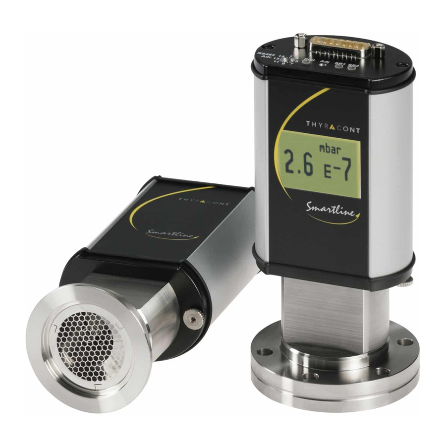
4.2 Bedienung des VSH Die Status-LED des VSH signalisiert folgende Betriebszustände: Die Schaltpunkt LEDs leuchten, sobald das zugehörige Relais angezogen ist. VSH-RS485-200116... - Page 12 Die Modelle VSH87DL, VSH88DL und VSH89DL verfügen zudem über ein gelb hinterleuchtetes LCD zur Anzeige des gemessenen Drucks. Liegt eine Betriebsstörung vor, wird dies durch ein rot hinterleuchtetes Display si- gnalisiert. Zum Ändern der Anzeigeeinheit (mbar, Torr, hPa) während die Spannungsversorgung angeschlos- sen wird die »Adj«...
- Page 13 Bedienschema Adj-Taster für die Funktionen »Degas« und »Nachjustieren« : VSH-RS485-200116...
-
Page 14: Degas
4.3 Degas Ablagerungen und adsorbierte Gasmoleküle auf den Elektroden des Heißkatho- densensors können zu erhöhtem Ausgasen im Ultrahochvakuum führen sowie andererseits Instabilitäten im Mess-Signal verursachen. In diesem Fall ist es an- gebracht, bei einem Druck unterhalb 2,0x10 mbar die Anode des Sensors durch Ausheizen von Ablagerungen und adsorbierten Gasmolekülen zu reinigen. -
Page 15: Nachjustieren
Die Druckmessung läuft während des Degas-Vorgangs weiter. Dieser endet auto- matisch nach ca. 3 Minuten, kann jedoch jederzeit abgebrochen werden, indem Pin 9 nochmals kurz wie oben beschrieben beschaltet wird. Während des Degas- Vorgangs blinkt die Status-LED des VSH rot. Degas-Steuerung per Software-Kommando Siehe Abschnitt 5.8 4.4 Nachjustieren... -
Page 16: Ausheizen
Zum Justieren den Gummistopfen über dem Taster »Adj« entfernen (1), dann mit einem dünnen Schraubendreher oder ähnlichem Hilfsmittel mehrmals kurz auf den Taster drücken (2), bis die Status-LED schnell orange zu blinken beginnt. Nach 3 s ohne weiteren Tastendruck signalisiert langsames Blinken, dass der Transmitter nun nachjustiert werden kann. -
Page 17: Kommunikation
Wert zwischen 1 und 16 einzustellen (2). Danach den Gummistopfen wieder ein- setzen. Bei der Kommunikation werden die Telegramme gemäß Thyracont Protokoll Versi- on V2 als ASCII-Code übertragen. Ausführliche Informationen hierzu finden Sie in der gesonderten Beschreibung »Thyracont Communication Protocol«. -
Page 18: Parameterübersicht
5.2 Parameterübersicht Command Code Type of Device Product Name Serial Number Device Serial Number Head (Sensor) Version Device Version Firmware Version Bootloader Baud Rate Response Delay Device Restart Measurement Range Measurement Value Measurement Value 1 (Pirani) Measurement Value 3 (Hot Cathode) Display Unit Display Orientation Relay 1... -
Page 19: Geräte-Parameter Und Information
5.3 Geräte-Parameter und Information Type of Device (TD): Abfragen des Gerätetyps, z.B. VSH208 Product Name (PN): Abfragen des Produktnamens (entspricht der Artikelnummer) Serial Number Device (SD): Abfragen der Geräte-Seriennummer Serial Number Head (SH): Abfragen der Seriennummer des Sensorkopfes Version Device (VD): Abfragen der Hardware-Versionsnummer des Geräts Version Firmware (VF): Abfragen der Firmware-Versionsnummer des Geräts... -
Page 20: Messwertabfrage
5.4 Messwertabfrage Measurement Range (MR): Abfragen des Messbereichs Measurement Value MV: Abfragen des aktuell gemessenen Druckwertes Measurement Value M1: Abfragen des aktuell vom Pirani-Sensor gemessenen Druckwertes Measurement Value M3: Abfragen des aktuell vom Heißkathodensensor gemessenen Druckwertes. Bei ausgeschalteter Heißkathode wird der Fehlercode »_ SEDIS« zurückgegeben. 5.5 Displayfunktionen Display Unit (DU): Abfragen und Einstellen der für das LCD Display des Transmitters verwendeten... -
Page 21: Schaltpunkte
5.6 Schaltpunkte Das VSH besitzt 2 unabhängige, potentialfreie Relais-Schalter. Diese sind als Um- schalter gemäß der in 3.3.2 beschriebenen Pinbelegung am Anschluss-Stecker nach außen geführt. Relay R1, R2: Die Relais können unabhängig voneinander für verschiedene Schaltmodi konfigu- riert werden, der Parameter dient zum Abfragen und Einstellen dieser Schaltmodi. Einstellung T[p1] F[p2]: Hier werden zwei Druckwerte T[p1] (true) und F[p2] (false) übertragen. -
Page 22: Nachjustieren
Die Einstellung T[p1] = F[p2] ist nicht erlaubt! Ein zu kleiner Ab- stand der beiden Schaltdrücke kann zum Flackern und zur Beschä- digung des Relais führen! Einstellung E: Relais zieht an bei Gerätefehler. Einstellung !E: Relais fällt ab bei Gerätefehler. Einstellung U: Relais zieht an bei Messbereichsunterschreitung. -
Page 23: Sensor Parameter
Um optimale Ergebnisse beim Nachjustieren zu erzielen, empfeh- len wir vor jedem Abgleich eine Warmlaufphase von mindestens 10 Minuten beim jeweiligen Kalibrierdruck zu beachten. 5.8 Sensor Parameter Degas (DG) Ablagerungen und adsorbierte Gasmoleküle auf den Elektroden des Heißkatho- densensors können zu erhöhtem Ausgasen im Ultrahochvakuum führen sowie an- dererseits Instabilitäten im Mess-Signal verursachen. - Page 24 figuriert werden: »0«: Keine Wertangleichung, d.h. direktes Umschalten zwischen Pirani und Heißkathode bei 4,0x10 mbar (Heißkathode ein bei 4,0x10 mbar / aus bei 6,0x10 mbar) »1«: Kontinuierliche Wertangleichung im Bereich 1,0 ... 2,0x10 mbar (Heißkathode ein bei 3,0x10 mbar / aus bei 4,0x10 mbar) (Default) »2«:...
- Page 25 Filament Control (FC) Der Bayard Alpert Heißkathoden-Sensor des VSH ist mit zwei Heiz-Filamenten ausgestattet. Dieser Parameter steuert, in welcher Weise die beiden Filamente benutzt werden: »0«: Filament 1 aktiv, bei Defekt wird auf Filament 2 umgeschaltet (Default) »1«: nur Filament 1 wird benutzt »2«: nur Filament 2 wird benutzt »3«:...
- Page 26 Korrekturfaktor C3 Heißkathode: 0,74 0,41 Skalierung Analogausgang - Analog Output Characteristic (OC) Die Skalierung des analogen Signalausgangs lässt sich mithilfe dieses Parameters per Softwarebefehl den Erfordernissen der Anwendung anpassen. Beispielsweise kann die Ausgangscharakteristik so eingestellt werden, dass das Signal zu Gerä- ten anderer Hersteller kompatibel ist.
-
Page 27: Vacugraph Software
5.9 VacuGraph Software Die Software VacuGraph wurde speziell für den Einsatz mit Thyracont Messgerä- ten entwickelt und läuft auf den Betriebssystemen Windows, Linux, MacOS und Android. Sie ermöglicht neben dem Plotten und Speichern von Messdaten auch das be- queme Konfigurieren aller Geräteparameter. -
Page 28: Wartung Und Service
Elektronik oder Sensor Gerät einschicken oder »ERROR1« via RS485 / defekt Sensor ersetzen Status LED dauer-rot Status LED dauer-orange Heißkathode Filament 1 ggfs. Sensor ersetzen defekt Access Code »7« via Fehlermeldung / Warnung siehe gesonderte RS485 Beschreibung Thyracont Communication Protocol VSH-RS485-200116... - Page 29 VSH-RS485-200116...
-
Page 30: Technische Daten
7 Technische Daten Messprinzip Wärmeleitfähigkeit Pirani / Heißkathode Bayard Alpert, gasartabhängig Messbereich 1000 - 5,0x10 mbar (750 - 5,0x10 Torr) Max. Überlast 4 bar abs. Genauigkeit 1000 ... 10 mbar: ca. 30% v. Messwert 10 ... 1,0x10 mbar: 10% v. Messwert Wiederholbarkeit 10 ... - Page 31 Spannungsversorgung 20 - 30 VDC Leistungsaufnahme max. 8 W, zusätzlich 1 W für Degas, 0,8 W für Relais und LCD Ausgangssignal 0 - 10 VDC, min. 10 k , Messbereich 1,219 - 8,6 VDC, logarithmisch Serielle Schnittstelle RS485: 9,6 ... 115 kBd, 8 databit, 1 stopbit, no parity Schaltausgänge 2x Relais, potentialfrei...
-
Page 32: Konformitätserklärung
8 Konformitätserklärung VSH-RS485-200116... - Page 33 3.3 Electrical Connection ......3.3.1 Operation with Thyracont Display Unit ... . .
-
Page 34: Safety Instructions
1 Safety Instructions Read and follow the instructions of this manual Inform yourself regarding hazards, which can be caused by the product or arise in your system Comply with all safety instructions and regulations for accident prevention Check regularly that all safety requirements are being complied with Take account of the ambient conditions when installing your VSH;... -
Page 35: Vacuum Transducer Vsh
2.1 For Orientation These operating instructions describe installation and operation of products with article numbers VSH87D, VSH88D, VSH89D, VSH87DL, VSH88DL, VSH89DL. The article number can be found on the product’s type label. Technical modificati- ons are reserved without prior notification. -
Page 36: Product Description
The VSH vacuum transducer is measuring total gas pressure in the range of 5.0x10 - 1000 mbar. The transducer can be connected to Thyracont display and control units or to customer related power supply and evaluation units in complian- ce with pin assignment. -
Page 37: Installation
3 Installation 3.1 Notes for Installation Unauthorized modifications or conversions of the instrument are not allowed! Installation location: Indoor For not fully air conditioned open buildings and operation rooms: Temperature: +5 C ... +60 C Rel. humidity: max. 80% up to 30 C, max. 50% at 40 C, non-condensing Ambient pressure: 860 - 1060 hPa (mbar) 3.2 Vacuum Connection Dirt and damage, especially at the vacuum flange, have an adver-... -
Page 38: Electrical Connection
3.3 Electrical Connection 3.3.1 Operation with Thyracont Display Unit For operation of the transducer with a Thyracont display and control unit a suitable measurement cable must be used (see accessories). Do not connect or disconnect the transducer when the cable is on circuit! Connect the cables plug to the transducer and secure it with the screw. -
Page 39: Operation With Other Supply And Evaluation Units
3.3.2 Operation with other Supply and Evaluation Units The transducer can be operated with other customer related display units or volta- ge supplies. The electrical connection is to be made by means of suitable cables considering EMI demands and according to the pin description shown below: Socket Sub-D, 15-pole, male Pin1:... -
Page 40: Operation
4 Operation 4.1 General Measurement Principle The VSH vacuum transducer is equipped with an internal combination sensor of type Pirani / Hot Cathode. The Pirani principle uses the heat conduction of gases for measuring vacuum. A sensor filament in a Wheatstone circuit is heated to a constant temperature, so the bridge voltage is a measure for total gas pressure. -
Page 41: Operation Of The Vsh
4.2 Operation of the VSH The status LED of the VSH signalizes the following operational states: The switchpoint LEDs are on when the related relay is activated. VSH-RS485-200116... - Page 42 In addition models VSH87DL, VSH88DL and VSH89DL have an LCD with yellow backlight that displays the measured actual pressure. In case of an operation error or malfunction the display is illuminated by a red back- ground color. In order to change the display unit (mbar, Torr, hPa) hold the »Adj«...
- Page 43 How to access »Degas« and »Adjustment« functions by means of the »Adj« key: VSH-RS485-200116...
-
Page 44: Degas
4.3 Degas Deposition or adsorbed gas molecules on the electrodes of the hot cathode sensor may lead to increased degassing in ultrahigh vacuum or even cause instabilities of the measurement signal. In such cases it is appropriate to clean the anode of the sensor from such deposited material and adsorbed gas molecules by degassing. -
Page 45: Readjustment
The degas procedure will stop automatically after approx. 3 minutes, but can be cancelled any time by again connecting pin 9 in the above mentioned manner. While the sensor is degassing the red status LED is flashing slowly in red color. Degas Control via Software Command See section 5.8. -
Page 46: Bake-Out
For adjustment first remove the rubber cap above the »Adj« button (1), then press the pushbutton several times by means of a screwdriver or other suitable tool (2) until the status LED starts quickly flashing orange. After further 3 s a slowly fla- shing status LED signalizes that the transducer now can be readjusted by pushing the button once again. -
Page 47: Communication
(2). Afterwards insert the rubber cap again. Communication telegrams are transmitted as ASCII text according to the Thyra- cont protocol version V2. Detailed information is provided in the separate descrip- tion »Thyracont Communication Protocol«. Download link: www.thyracont-vacuum.com/en/support/downloadcenter/ Interface Parameter: 9.6 / 14.4 / 19.2 / 38.4 / 57.6 / 115.2 kBd, 8 databits, 1 stopbit, no parity... -
Page 48: Survey Of Commands
5.2 Survey of Commands Command Code Type of Device Product Name Serial Number Device Serial Number Head (Sensor) Version Device Version Firmware Version Bootloader Baud Rate Response Delay Device Restart Measurement Range Measurement Value Measurement Value 1 (Pirani) Measurement Value 3 (Hot Cathode) Display Unit Display Orientation Relay 1... -
Page 49: Device Parameters And Information
5.3 Device Parameters and Information Type of Device (TD): Query of device type, e.g. VSH208 Product Name (PN): Query of product name (article number) Serial Number Device (SD): Query of device serial number Serial Number Head (SH): Query of sensor head serial number Version Device (VD): Query of the device’s hardware version Version Firmware (VF):... -
Page 50: Measurement Query
5.4 Measurement Query Measurement Range (MR): Query measurement range of the gauge Measurement Value MV: Query current pressure measurement Measurement Value M1: Query current pressure measurement of the Pirani sensor Measurement Value M3: Query current pressure measurement of the hot cathode sensor. If the hot cathode sensor is switched off, error code »_ SEDIS«... -
Page 51: Switchpoints
5.6 Switchpoints The VSH provides 2 independent, potential-free relay switchpoints. These are available as change-over switches at the connector according to the pin assi- gnment described in section 3.3.2. Relay R1, R2: The relays can be configured independently for various switching modes. The pa- rameter is used to query and set these switching modes. -
Page 52: Readjustment
Setting T[p1] = F[p2] ist not allowed! A gap between the thresholds being too small may result in flickering of the relay and can even cause damage to the relay! Setting E: Relay closes in case of a device error. Setting !E: Relay opens in case of a device error. -
Page 53: Sensor Parameters
To achieve optimum results of the adjustment we recommend to consider a warm-up of at least 10 minutes at the appropriate cali- bration pressure before any adjustment. 5.8 Sensor Parameters Degas (DG) Deposition or adsorbed gas molecules on the electrodes of the hot cathode sensor may lead to increased degassing in ultrahigh vacuum or even cause instabilities of the measurement signal. - Page 54 »0«: no transition, but direct switch-over between Pirani and hot ca- thode sensor at 4.0x10 mbar (hot cathode on at 4.0x10 mbar / off at 6.0x10 mbar) »1«: continuous transition in the range 1.0 ... 2.0x10 mbar (hot cathode on at 3.0x10 mbar / off at 4.0x10 mbar) (default) »2«:...
-
Page 55: Filament Control Fc
Filament Control (FC) The Bayard Alpert hot cathode sensor of the VSH is equipped with two heating filaments. This parameter defines in which manner these filaments will be used: »0«: filament 1 active, in case of a defect the sensor will switch to filament 2 (default) »1«: only filament 1 will be used... - Page 56 Scaling of Output - Analog Output Characteristic (OC) The analog output characteristic can be scaled according to application require- ments by adjusting this parameter via software command. The voltage output cur- ve can, for example, be modified to become compatible with transducers of other brand labels.
-
Page 57: Vacugraph Software
5.9 VacuGraph Software VacuGraph software has been especially developed for use with Thyracont gauges and is compatible with operating systems Windows, Linux, MacOS and Android. VacuGraph features plotting and saving of measurement data as well as comfor- table configuration of all device parameters. -
Page 58: Maintenance And Service
»ERROR1« via RS485 / sensor replace sensor status LED cont. red status LED cont. orange hot cathode filament 1 replace sensor if defective appropriate access code »7« via error message / warning see separate RS485 documentation Thyracont Communication Protocol VSH-RS485-200116... - Page 59 VSH-RS485-200116...
-
Page 60: Technical Data
7 Technical Data Measurement principle heat conduction Pirani / hot cathode Bayard Alpert, depending on gas type Measurement range 1000 - 5.0x10 mbar (750 - 5.0x10 Torr) Max. overload 4 bar abs. Accuracy 1000 ... 10 mbar: approx. 30% f. reading 10 ... - Page 61 Voltage supply 20 - 30 VDC Power consumption max. 8 W, additionally 1 W for degas, 0.8 W for relays and LCD Output signal 0 - 10 VDC, min. 10 k , measuring range 1.219 - 8.6 VDC, logarithmic Serial interface RS485: 9.6 ...
-
Page 62: Declaration Of Conformity
8 Declaration of Conformity VSH-RS485-200116... - Page 63 VSH-RS485-200116...
- Page 64 VSH-RS485-200116...
Need help?
Do you have a question about the VSH87D and is the answer not in the manual?
Questions and answers