Table of Contents
Advertisement
Available languages
Available languages
Quick Links
INSTRUCTION
EN
CTR-ADD
i
Read this instruction before installation
and wiring of the product
Consult documentation in all cases where this symbol
is used, in order to find out the nature of the potential
hazards and any actions to be taken
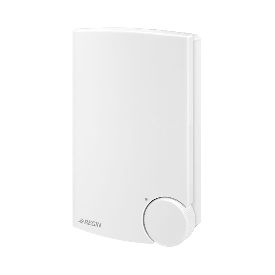
Triac controller for proportional control
of electric heating, add-on unit
CTR-ADD is a complete proportional controller for electric heating.
It has automatic voltage adjustment. It has no sensor input but is
intended to be controlled by another CTR unit.
CTR-ADD is only intended for electric heating control. The control
principle makes it unsuitable for motor- or lighting control.
CTR-ADD cannot control 3-phase loads.
Installation
Remove the front. The locking screw is behind the set-point knob.
Mount CTR‑ADD vertically with the cooling flange at the top. Use
screws with a maximum head diameter of 5.5mm.
CTR-ADD emits approx. 20W of heat which must be dissi-
pated. Ambient temp.: 0 - 30°C, non-condensing.
Protection class: IP20.
Wiring
Supply voltage
Terminals 1 and 2. Not polarity sensitive.
Supply voltage: 200 - 415V AC, 50 - 60 Hz with automatic voltage
adjustment. Maximum current 16A.
1 2 U 3 4 U
I I
Figure 1: Wiring of supply voltage and load
The supply voltage to CTR-ADD should be wired via an all-pole
switch with a minimum contact gap > 3mm. The cooling flange is live.
Load
Terminals 3 and 4.
Resistive single- or two-phase heater
Maximum load:
3680W at 230V (16A)
6400W at 400V (16A)
Minimum load:
230W at 230V (1A)
400W at 400V (1A)
Control signal
Terminals I and I. Not polarity sensitive.
Wire to terminals U and U in the main unit.
CTR-ADD
1 2 U 3 4 U
I I
CTR...
K 1 2 U 3 4 U K G G
Figure 2: Wiring of control signal
CTR-ADD is galvanically separate from the main unit. They may
therefore be supplied from different phases. The CTR-ADD control signal
has high potential compared to neutral and earth (>200V). Thus, wiring of
the control signal must comply with local codes for line voltage installa-
tions. The control signal must be wired so that the signal is cut when the
supply voltage is cut.
CTR-ADD
Control principle
CTR-ADD pulses the full load On - Off parallel to the master unit it is
connected to.
CTR‑ADD has zero phase‑angle firing to eliminate RFI.
Start-up and fault finding
Be careful when working in the CTR-ADD. All internal compo-
nents including the cooling flange are at line voltage potential. Never
leave the unit under power without the front cover on.
1.
Check that all wiring is correct.
2.
Measure the resistance between terminals 3 - 4: At 230V:
14.4Ω<R<230Ω. At 400V:25Ω<R<400Ω.
3.
Connect supply voltage and twist the setpoint knob of the master
unit between end stops. Check that the LED on the side of CTR-
ADD goes on and off at the same time as the LED of the master
unit. Check with a clamp‑on ammeter that current is flowing to
the heater.
Anything wrong?
1.
Disconnect supply power. Remove the control signal wiring from
terminals I and I. Reconnect power. The LED should be continu-
ously off and no current should flow to the heater. Disconnect
power and connect the terminals I and I to the terminals 1 and 2.
Reconnect power. The LED should be continuously on and full
current should flow to the heater.
2.
If everything is OK this far the CTR-ADD is OK and the fault
must be found elsewhere.
Low Voltage Directive (LVD) standards
This product conforms to the requirements of the European Low Volt-
age Directive (LVD) standards EN 60669-1 and EN 60669-2-1.
EMC emissions & immunity standards
This product conforms to the requirements of the EMC Direc-
tive 2004/108/EC through product standards EN 61000-6-1 and
EN 61000-6-3.
RoHS
This product conforms to the Directive 2011/65/EU of the European
Parliament and of the Council.
Contact
AB Industrietechnik Srl
Via Julius Durst, 70 - 39042 Bressanone (BZ) - Italy
Tel. +39 0472/830626 ‑ Fax +39 0472/831840
www.industrietechnik.it - info@industrietechnik.it
1
Advertisement
Table of Contents

Summary of Contents for industrie technik CTR-ADD
- Page 1 INSTRUCTION Control principle CTR-ADD CTR-ADD pulses the full load On - Off parallel to the master unit it is connected to. 1 2 U 3 4 U CTR‑ADD has zero phase‑angle firing to eliminate RFI. Start-up and fault finding Figure 1: Wiring of supply voltage and load Be careful when working in the CTR-ADD.
- Page 2 Montare l’unità CTR-ADD in posizione verticale con Se è tutto in ordine, il CTR-ADD è a posto e il guasto deve es- l’aletta di raffreddamento in alto. È possibile utilizzare viti con un sere ricercato altrove.
- Page 3 Die Klemmen U und U mit dem Hauptregler verbinden. Etwas falsch gemacht? Trennen Sie die Versorgungsspannung. Entfernen Sie das Der CTR-ADD ist ein kompletter Regler für die Regelung von Elektro- Reglsignal von den Klemmen I und I. Spannung wieder an- heizregistern mit automatischer Spannungsnachführung. Er verfügt CTR-ADD schließen.
- Page 4 Ce produit répond aux exigences de la directive 2004/108/CE du Raccordement electrique Le CTR-ADD est séparé du CTR principal. Il est préférable de les Parlement européen et du Conseil (CEM) au travers de la conformité alimenter à partir de différentes phases. Les signaux du CTR-ADD ont de aux normes EN 61000-6-1 et EN 61000-6-3.


Need help?
Do you have a question about the CTR-ADD and is the answer not in the manual?
Questions and answers