
Related Manuals for industrie technik evolution AHU-XXXSX1 series


Summary of Contents for industrie technik evolution AHU-XXXSX1 series
- Page 1 USER MANUAL ROOM CONTROLLER EVOLUTION SERIES AHU-xxxSx1 05/03/2018 Version 1.0.4...
-
Page 2: Table Of Contents
TABLE OF CONTENT Technical features ............................6 Code selection ..............................6 Display, keypad and icons ..........................7 Quick access parameter setting .........................8 • Keypad lock ......................................8 • Switch on and off ....................................8 • Setpoint and setpoint offset configuration ............................9 • Fan operating mode .................................... - Page 3 17. Humidification ............................42 • Using a modulating humidifier: ................................42 • Using an on/off humidifier:................................. 43 • humidification authorization for humidifier not managed by the controller: ..................43 18. Humidity supply limits function ........................44 • Low dehumidification limit: ................................44 Low limit in dehumidification mode with modulating control: .......................
- Page 4 Regulation of on/off damper based on free cooling/heating and CO ..................79 » Regulation of on/off damper based on dehumidification ......................79 » • Modulating damper:................................... 80 Regulation of modulating damper based on free cooling/heating ....................81 » Regulation of modulating damper based on CO ........................
- Page 5 • MODBUS VARIABLES FOR CONTROLLER STATUS: ........................137 • MODBUS VARIABLES FOR OPERATING PARAMETERS ......................141 • Default parameters reset via MODBUS ............................154 • Clock setting via MODBUS ................................154 • MODBUS communications alarm..............................154 • MODBUS connection diagram ................................ 155 42.
-
Page 6: Technical Features
AHU room controller 1. Technical features Power: 110...230 Vca ±10%, 50/60 Hz Power consumption: max 1.3W Operating temperature: 0 - 50°C Display: backlit LCD display Inputs: 2 potential free contacts 2 or 3 NTC10K sensors USB for parameter configuration and software updates Outputs: 3 analogue outputs 0... 10 V (R >... -
Page 7: Display, Keypad And Icons
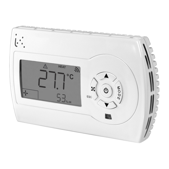
3. Display, keypad and icons HEAT HEAT HEAT COOL COOL COOL °C°F °C°F °C°F HEAT COOL °C°F HEAT HEAT COOL COOL °C°F °C°F Display A Display B On/Off Timer extension on flashing Clock setting continuously displayed Economy or boost function on General alarm Communications alarm Parameters menu... -
Page 8: Quick Access Parameter Setting
HEAT COOL ON = heat recovery on °C°F OFF = heat recovery off OFF blinking = heat recovery off for free cooling/heating or due to heat exchanger frost protection alarm ON/OFF alternating blinking = modulating bypass damper of the heat exchanger with cross-flow partially open (free heating or free cooling in progress) Display C time zone number on Free cooling or free heating on Keyboard On/Off, navigation and confirm key Change setpoint, navigation and value entry keys Speed type key and ESC operation in navigation Manual season or occupation change key or operating mode (see “MODE button functionality” page 10) 4. Quick access parameter setting The controller carries out the following operations with a simple button press: •... -
Page 9: Setpoint And Setpoint Offset Configuration
or 017=2 (DI2) or 019=9 (AI1 used as DI) or 021=9 (AI2 used as DI) or 023=9 (AI3 used as DI)). Example for digital input 1 (015=2): Unit ON= (016=0) Unit OFF= (016=0) Unit ON= (016=1) Unit OFF= (016=1). To switch the unit on/off using the timer periods, configure the 199=1 parameter and set the timer switch on timer periods (see “6. -
Page 10: Mode Button Functionality
• MODE button functionality Depending on the value of parameter 195, the function is selected by quick access by pressing the MODE button. The other 2 functions can, however, be accessed by pressing the buttons. Access to the rapid function using the MODE button: • If 195=0 (quick access to the local season change configuration if no contact is configured as remote season change) Press the button, the “HEAT” (for heating) or “COOL” (for cooling) icon flashes depending on the current configuration and the same flashing text appears on display B. Press the button to change the setting. The value is automatically saved. To exit the menu, wait for 4 seconds or press the button. • If 195=1 (quick access to the timer extension configuration) The extended running function extends operation with the base setpoint by excluding the economy function and the “non-occupied holiday” function for a time corresponding to parameter 198 if the timer function parameter 199=0. - Page 11 Non-quick access to the functions using the keypad ■ If the MODE button quick access function is set to local season change (195=0), to access the other functions, press the buttons at the same time to enter the menu for changing the extended running and operating mode functions: Parameter Description...
-
Page 12: Date And Time Setting (Model Ahu-Xxcsx1)
■ If the MODE button quick access function is set to operating mode (195=2), to access the other functions, press the and buttons at the same time to enter the menu for changing the seasonal change function and timer extension. Parameter Description Default Local season change (local season change configuration for 2-pipe systems): HEAT HEAT COOL HEAT=Heating mode CooL=Cooling mode Timer extension noOC=timer extension off noOC noOC OC=with timer extension (for the duration corresponding to the parameter 198 the economy/boost function and the non-occupied/holiday function are excluded if 199=0, the appliance stays switched on if 199=1). Press the button to select a parameter and the button to enter change mode; display B flashes with the current parameter value. Then press the button to change the value. Press the button to save the configuration, or the button to quit without saving the changes. - Page 13 Timer period 1 Time Timer period 2 Time Timer period 3 Time Timer period 4 Time Operating mode Time ECO = economy/boost mode, NO ECO = normal mode (control with base setpoint). • With 199=1, in an ON period, the appliance is switched on. Outside the ON periods, the controller is switched off, and only the frost protection function is activated if parameter 188=1. Timer period 1 Time Timer period 2 Time Timer period 3 Time Timer period 4 Time...
- Page 14 1--7 Press the button, the screen appears with the number 1 flashing corresponding to timer period 1: Press the button to select the timer period to be modified. Press the button and the screen is displayed showing the day of the flashing timer period: Press the button to select the required day. Press the button, the screen displays the day, timer period number and the starting time (ON) of the flashing period: 06 00 Press the button to select the desired hour. Press the button, the timer period starting time stops flashing and is saved to the memory. The minutes field of the start of the selected timer period starts flashing. Press the button to select the desired minutes. Press the button, the minutes of the starting time of the timer period stop flashing and are saved to the memory. The screen for setting the end time of the timer period displays: 08 00 Press the button to select the desired hour. Press the button, the timer period end time stops flashing and is saved to the memory. The minutes field of the end of the selected timer period starts flashing. Press the button to select the desired minutes. Press the button, the minutes of the end time of the timer period stop flashing and are saved to the memory. The screen for selecting the timer period day is displayed (flashing). Press the button to return to the timer period selection menu: Press the button to return to the main menu or repeat the procedure to set another timer period. Parameter Description Timer period settings menu Timer period selection...
-
Page 15: Duplication Of Timer Periods (Model Ahu-Xxcsx1)
7. Duplication of TIMER PERIODS (Model AHU-xxCSx1) It is possible to copy the settings of the timer periods of a day on another single day or on 5 days from Monday to Friday or on 2 days from Saturday to Sunday. To copy the timer periods from one day to another day follow the procedure described below. Press the buttons together, the main menu is displayed: yMdH Press the button, the following screen is displayed: Mo Mo Day to be copied: destination day Press the button, the day to be copied flashes. Select the day to copy with the buttons. Press the button, the day to which the periods will be copied starts to flash. If you set “MF” as the destination, the selected day will be copied to the days from Monday to Friday. If you set the destination as “SS”, the selected day will be copied to the days of Saturday and Sunday. Press the button to make the duplication or press the button to cancel. -
Page 16: Control Sensors
8. Control sensors It is possible to set regulation with - 2-pipe fixed point (014=0) or 4-pipe fixed point (014=3), - 2-pipe compensated (014=1) or 4-pipe compensated (014=4), - cascade (014=2). Depending on the type of control desired, select the appropriate sensors according to the table below: Types of control Control sensor Settings Internal: 019≠1 and 021≠1 and 023≠1 and 106=0 Room Remote: 019=1 (AI1) or 021=1 (AI2) or 2 or 4-pipe fixed point 023=1 (AI3) and 106=100 Supply 019=2 (AI1) or 021=2 (AI2) or 023=2 (AI3) -
Page 17: Operating Setpoint, Economy/Boost, Holiday Modes
9. Operating setpoint, ECONOMY/BOOST, HOLIDAY MODES If one of the digital contacts is configured as a “non-occupied/holiday” remote contact 015=3 (DI1) or 017=3 (DI2) or an ana- logue input is configured as a “non-occupied/holiday” contact 019=10 (AI1) or 021=10 (AI3) or 023=10 (AI3) the “non-occupied/ holiday” mode can be activated if the corresponding contact is in the appropriate position (see “36. Digital and analogue input logic” page 126). 2-pipe systems (014= 0, 1): In the “non-occupied/holiday” mode, the heating setpoint is decreased by 121 (see the 2-pipe heating graph, WHS), the cooling setpoint is increased by 121 (see the 2-pipe cooling graph, WCS). 4-pipe systems (014=2, 3, 4): In the “non-occupied/holiday” mode, the heating activation point is decreased by 121 (see 4-pipe graph, WHS) and the cool- ing activation point is increased by 121 (see 4-pipe graph, WCS). - Page 18 2-pipe graph (analogue output, cooling mode) 2-pipe graph (digital output, cooling mode) Temp. Temp. Temp Temp. Temp. ECONOMY ECONOMY ECONOMY ECONOM ECONOMY ECONOMY HOLIDAY HOLIDAY Temp. Temp. HOLIDAY HOLIDAY HOLIDAY HOLIDAY Temp Temp. Temp. (120 or 121) (120 or 121) positive positive (120 or 121)
- Page 19 4-pipe graph (analogue outputs) Temp. ECONOMY HOLIDAY Temp. positive positive 109: 4-pipe setpoint WCS: activation point, cooling mode WHS: activation point, heating mode Note: the Boost function ( negative) is not available in 4-pipe mode. Outputs It is possible to display the operating setpoint by configuring the parameter 193 or 194 to 6. In this case, in heating mode, the value corresponding to WHS is displayed, in cooling mode the value corresponding to WCS is displayed. If no contacts are configured in “non-occupied/holiday” or “energy saving / boost” mode, and if the operating mode has Temp been set manually with timer periods (Mod=tiMb) and the timer period function 199=0 (see “4.
-
Page 20: Batteries For Temperature And Humidity Control
10. Batteries for temperature and humidity control The configuration for the AHU batteries for temperature and humidity control is carried out using the following parameters - heating type battery 002, - cooling type battery 003, - post-heating type battery 004. - humidifier type battery 006. - dehumidifier type battery 007. Battery Type of battery Setting No heating battery 002=0 Modulating electrical resistance 002=1 Heating battery Modulating heating valve 002=2 Electrical resistance on/off 002=3 Heating valve on/off 002=4 No cooling battery 003=0 Cooling battery... - Page 21 030=4 (AO1) or Modulating cooling valve 031=4 (AO2) or 032=4 (AO3) 025=5 (DO1) or 026=5 (DO2) or Cooling valve on/off 027=5 (DO3) or 028=5 (DO4) or 029=5 (DO5) 030=5 (AO1) or Modulating mixed-use valve 031=5 (AO2) or 032=5 (AO3) 025=6 (DO1) or 026=6 (DO2) or Mixed-use valve on/off 027=6 (DO3) or...
-
Page 22: Logic Of Heating And Cooling Batteries
11. Logic of heating and cooling batteries The operating mode of the heating and cooling battery is based on the following parameters: - 014: type of controller selected, - 002: type of heating battery, - 003: type of cooling battery. 100% • 2-pipe HEATING controller (014=0 or 1) Treg The “HEAT” icon is displayed to indicate that the heating mode is active. Modulating controller: • The PI type controller operates in the following way for modulating control: OUTH OUTC OUTH 100% 100% 100% Treg... -
Page 23: 2-Pipe Heating Control (014=0 Or 1) Without Mid-Season Mode (013=0)
100% • 2-pipe HEATING control (014=0 or 1) without mid-season mode (013=0) Treg The “COOL” icon is displayed to indicate that cooling mode is active. OUTH OUTC OUTH Modulating controller: • The PI type controller operates in the following way for modulating control: Treg 100% Treg Treg: control sensor WCS = 108 if the controller is set at a fixed point (014=0) or calculated setpoint based on compensation (if 014=1) OUT: modulating output: - modulating valve if 003=1 and 030=4 (AO1) or 031=4 (AO2) or 032=4 (AO3). -
Page 24: 2-Pipe Cooling Control (014=0 Or 1) With Mid-Season Mode (013=1)
• 2-pipe COOLING control (014=0 or 1) with mid-season mode (013=1) Treg The “COOL” icon is displayed to indicate that cooling mode is active. If there is a sudden reduction in the temperature during the summer, the mid-season mode can be used to warm up using a heating element which can be modulating or on/off. 100% Mid-season mode with modulating heating element: OUTC Modulating COOLING 100% Supply setpoint Supply temp Treg 123/2 Treg: control sensor WCS = 108 if the controller is set at a fixed point (014=0) or calculated setpoint based on compensation (if 014=1) 124: differential activation of heating in the summer season 114: proportional band of heating controller OUT: modulating electrical resistance if 002=1 and 030=6 (AO1) or 031=6 (AO2) or 032=6 (AO3). -
Page 25: 4-Pipe Controller (014=3 Or 4)
• 4-pipe controller (014=3 or 4) 100% In 4-pipe mode, the operating season is automatically selected based on the room temperature, the 4-pipe room setpoint 109 if 014=3 or the calculated winter compensation setpoint if 014=4 and 130=2 or 3, the neutral zone 123. OUTH OUTC Based on the controller selection, 2 setpoints are calculated: HEATING COOLING if 014=3: modulating modulating - WHS = heating setpoint =109 - (123/2) - WCS = cooling setpoint =109 + (123/2) Supply temp. if 014=4: Supply - WHS = calculated winter compensated setpoint - (123/2) setpoint - WCS = calculated winter compensated setpoint + (123/2) If the temperature rises above WCS, the operating season is considered to be cooling and the “COOL”... - Page 26 If the operating temperature rises above WCS, the modulating cooling valve starts to open. The icon is displayed. The valve can be controlled with PI action if the integral time 117 does not equal 0 or with proportional action only if 117=0. The icon switches off if the valve closes when Treg <= WCS. Modulating heating control and cooling on/off: • The PI type controller operates in the following way for modulating control: OUTH OUTC 100% 100% Treg Treg Treg: control sensor WHS = calculated heating setpoint OUTH OUTC WCS = calculated cooling setpoint 123: neutral zone 100% 122: hysteresis for on/off output. 100% 114: proportional heating band OUTH: modulating heating output: - modulating valve if 002=2 and 030=3 (AO1) or 031=3 (AO2) or 032=3 (AO3).
- Page 27 OUTH OUTC If Treg < (WHS - 122), the heating valve (or electrical resistance) is activated. The ) icon is displayed. If Treg >= WHS, the heating valve (or electrical resistance) is disabled. The ) icon is switched off. 100% If Treg > (WCS + 122), the cooling valve is activated. The icon is displayed. If Treg <= WCS, the cooling valve is deactivated and the icon is switched off. Treg Controlling modulating heating and cooling on/off: • The PI type controller operates in the following way for modulating control: OUTH OUTC 100% Treg...
-
Page 28: Cascade Control (014=2)
Treg • Cascade control (014=2) This type of operation is only possible if a modulating heating output and/or cooling output is defined, as shown below. 100% Supply setpoint modulating heating output: OUTC - modulating heating valve if 002=2 and 030=3 (AO1) or 031=3 (AO2) or 032=3 (AO3). Modulating - modulating electrical resistance if 002=1 and 030=6 (AO1) or 031=6 (AO2) or 032=6 (AO3). COOLING modulating cooling output: Supply temp. - Page 29 Control with a single heating valve: 100% OUTH Modulating HEATING Supply setpoint Supply temp. 123/2 114: proportional heating band 123: neutral zone 100% The PI heating controller controls the heating valve, taking the following control parameters into account: OUTH • supply temperature, Modulating • supply set - neutral_zone (123) / 2, HEATING • proportional band for heating supply control 114 Supply temp. • integral control time for heating supply 115. Supply setpoint 100% If the temperature of the supply sensor is lower than the supply set - 123 / 2, the heating output valve (or modulating...
-
Page 30: Mixed-Use Valve
Control with heating and cooling valve: 2 PI controllers control the modulating heating and cooling valves, based on the supply temperature, the calculated supply setpoint and the neutral zone 123. 100% OUTH OUTC HEATING COOLING modulating modulating Supply temp. Supply setpoint The PI heating controller controls the heating valve, taking the following control parameters into account: • supply temperature, • supply set - neutral_zone (123) / 2, • proportional band for heating supply control 114 • integral control time for heating supply 115. The PI cooling controller controls the cooling valve, taking the following control parameters into account: HEATING COOLING • supply temperature, • supply set + neutral_zone (123) / 2, •... -
Page 31: Post-Heating Battery Logic
13. Post-heating battery logic The post-heating battery can be used as battery for integration with the heating battery, as a post-heating battery following a reduction in temperature due to dehumidification, or as an additional heating stage. Post-heating can be carried out using a modulating valve (004=2), an on/off valve (004=4), a modulating resistance (004=1), or an on/off resistance (004=3). In addition, the post-heating battery uses the control sensor and the current operating setpoint for control. In post-heating or in the additional heating stage, the battery uses the post-heating setpoint (parameter 179) and is controlled based on the supply temperature. In this case, an analogue input must be defined as a supply sensor: 019=2 (AI1) or 021=2 (AI2) or 023=2 (AI3). Through the parameter 005 the post-heating battery's operation is selected: - 005=0 post-heating only, - 005=1 integration and post-heating. In the latter case, if no dehumidification is active, the post-heating battery works in integration mode; otherwise, in post-heating mode. - 005=2 additional heating stage. The control is proportional if the battery is modulating or on/off in other cases. The parameter 180 represents the proportional band or the hysteresis of the post-heating stage. -
Page 32: Modulating Integration Operation
180: proportional post-heating band If Tsup < 179 -180 post-heating or the additional heating stage is activated, the ) icon is displayed if the post-heating is a valve (or electrical resistance). If Tsup >= 179 post-heating (or the additional heating stage) is deactivated. The 100% icon switches off if the post-heating or the additional heating is a valve (or electrical resistance) and if the heating stage is also deactivated. Tsup • Modulating integration operation: 100% - integrational stage with valve: 004=2 and 030=7 (AO1) or 031=7 (AO2) or 032=7 (AO3). - integrational stage with electrical resistance: 004=1 and 030=8 (AO1) or 031=8 (AO2) or 032=8 (AO3). Tsup 100% Treg... -
Page 33: Supply Limits Function With Fixed-Point Control
HEATING COOLING 14. Supply limits function with fixed-point control Treg For fixed point control it is possible to take the supply limits into account to prevent the release of air into the supply duct which is too cold or too hot. It is possible to enable the upper and lower limits separately in a given season based on the values of parameters 125 and 127 respectively. The limit sensor is the supply sensor. Pair it with a sensor input 019=2 (AI1) or 021=2 (AI2) or 023=2 (AI3). If no supply sensor has been paired with an input sensor, the limit function is not taken into consideration. • Minimum limit: Volt Volt To enable the lower limits in cooling mode, set 125=1. To enable the lower limits in heating mode, set 125=2. Extractor fan Supply fan To enable the lower limits in heating and cooling modes, set 125=3. To disable this function, set 125=0. Pair the supply with an input:019=1 for input AI1 or 021=1 for input AI2 or 023=1 for input AI3. Supply fan Extractor fan Speed... -
Page 34: Low Limit In Cooling Mode With Modulating Control
Supply fan Low limit in cooling mode with modulating control: Val_lim_min_C Extractor fan Speed 100% Tlim Val_lim_min_C: theoretical value of the low limit output in cooling mode Tlim: temperature of the supply sensor 126: setpoint of low limit Val_lim_max_C 129: proportional limit band Control without dehumidification (139=0): When active, if the supply temperature falls below the minimum supply setpoint 126, the cooling valve is controlled consider- ing the lowest value between the theoretical output of the cooling control and the theoretical value of the Val_lim_min_C limit. -
Page 35: Maximum Limit
HEATING COOLING Val_lim_min_C • Maximum limit: Val_lim_min_H Treg To enable the high limit in cooling mode, set 127=1. To enable the high limit in heating mode, set 127=2. To enable the high limit in heating and cooling mode, set 127=3. To disable this function, set 127=0. Tlim High limit in heating mode with modulating control: Val_lim_max_C Val_lim_max_H Volt Volt Extractor fan Supply fan Tlim Supply fan Extractor fan Speed Speed Val_lim_max_H: theoretical value of the high limit output in heating mode 100% 100% Tlim: temperature of the supply sensor... -
Page 36: High Limit In Cooling Mode With Modulating Control
Tlim High limit in cooling mode with modulating control: Val_lim_max_C Volt Supply fan Tlim Extractor fan Val_lim_max_C: theoretical value of the high limit output in cooling mode Speed Tlim: temperature of the supply sensor 100% 128: setpoint of high limit 129: proportional limit band When active, if the supply temperature goes above the maximum supply setpoint 128, the cooling valve is controlled consider- ing the maximum value between the theoretical output of the cooling control and the theoretical value of the Val_lim_max_C... -
Page 37: Control With Setpoint Compensation
Tlim 15. Control with setpoint compensation Val_lim_min_C Val_lim_min_H The compensated setpoint allows an operating setpoint to be dynamically calculated according to the external temperature. In winter, it is normally used to raise the supply setpoint, when the external temperature falls. Val_lim_max_C In summer, it can calculate a room setpoint based on the external temperature to avoid having a large temperature difference Val_lim_max_H between the cooled internal environment and the external one. To use the setpoint compensation, select: - the operating mode 014=1 (2-pipe control with external compensation) or 014=4 (4-pipe control with external compensation), Tlim - type of compensation: 030=1 for compensation in cooling mode, Tlim 030=2 for compensation in heating mode, 030=3 for compensation in heating and cooling modes, - a sensor input to connect the external sensor: 019=3 for input AI1 or 021=3 for input AI2 or 023=3 for input AI3. Val_lim_max_C Val_lim_max_H •... -
Page 38: Compensation In The 2-Pipe Cooling Mode
• Compensation in the 2-pipe cooling mode: Two separate points are defined, as indicated in the charts below Tlim Example of compensation with 137 > 138. Set_comp_cool Set_comp_cool Set_comp_cool: summer compensated setpoint Te: external temperature Set_comp_cool 135:minimum external temperature for summer compensation 136:external maximum temperature for summer compensation 137:compensated setpoint corresponding to the minimum external temperature for summer compensation 135 138:compensated setpoint corresponding to the maximum external temperature for summer compensation 136 Example of compensation curve with 137 <... -
Page 39: Dehumidification
16. Dehumidification Dehumidification can be carried out in 3 modes: - using the same battery that is normally used for cooling, - using an on/off dehumidifier, - using a modulating dehumidifier, - using an external damper redulated on dehumidification - using modulating fans regulated on dehumidification Humidity can be controlled using the humidity sensor inside the controller (AHU-xxxxH1 models only) or using a remote humidity transmitter with output 0..10 V connected to input AI3 (023=6). • Use of the cooling battery for dehumidification: In case the cooling battery is used, it received two theoretical signals: - from the cooling controller - from dehumidification. The greater of these two signals is applied to the cooling battery. The dehumidification signal is calculated based on the curve indicated below: % dehum 141 / 2 H: value of the humidity detected by the internal or remote humidity sensor... -
Page 40: Using A Modulating Dehumidifier
• Using a modulating dehumidifier: The dehumidification signal is calculated based on the curve indicated below: % dehum 141 / 2 H: value of the humidity detected by the internal or remote humidity sensor WDS: dehumidification mode setpoint % dehum % dehum.: theoretical value percentage of dehumidification 142: humidity setpoint 141: humidity neutral zone 143: humidity proportional band 141 / 2... -
Page 41: Using An On/Off Dehumidifier
141 / 2 • Using an on/off dehumidifier: The dehumidification signal is calculated based on the curve indicated below: % dehum 141 / 2 H: value of the humidity detected by the internal or remote humidity sensor WDS: dehumidification mode setpoint Val_damper % dehum.: theoretical value percentage of dehumidification 142: humidity setpoint 141: humidity neutral zone 143: humidity proportional band Settings for dehumidification with on/off dehumidifier:... -
Page 42: Humidification
17. Humidification Humidification can be carried out by using: - an on/off humidifier, - a modulating humidifier. Humidity can be controlled using the humidity sensor inside the controller (AHU-xxxxH1 models only) or using a remote humidity transmitter with output 0..10 V connected to input AI3 (023=6). The presence of a one or more speeds on/off fan or a modulating supply fan is mandatory, otherwise humidification is not authorized. • Using a modulating humidifier: The humidification signal is calculated based on the curve indicated below: % hum 141 / 2 H: value of the humidity detected by the internal or remote humidity sensor WUS: humidifying operation setpoint % hum % hum: theoretical value percentage of humidification... -
Page 43: Using An On/Off Humidifier
141 / 2 • Using an on/off humidifier: The humidification signal is calculated based on the curve indicated below: % hum 141 / 2 H: value of the humidity detected by the internal or remote humidity sensor WUS: humidifying operation setpoint % hum: theoretical value percentage of humidification 142: humidity setpoint 141: humidity neutral zone 143: humidity proportional band Settings for humidification with on/off humidifier:... -
Page 44: Humidity Supply Limits Function
18. Humidity supply limits function It is possible to take the humidity limits into account for the supply to avoid air that is too humid or too dry to enter into the room. The low and high limits for humidity may be enabled separately, based on the value of the parameters 145 and 147 respectively. The limit sensor is the humidity supply sensor. Pair it with the sensor input AI3 (023=6). Set_comp_cool If no humidity supply sensor has been paired with an AI3 input sensor, the limit function is not taken into consideration. • Low dehumidification limit: To enable the low limit of dehumidification set the following parameters: - set the low limit control of humidity145=1, - pair the supply sensor with the AI3 input: 023=6 and put the JP1 jumper in the “3-2” position - define the minimum limit setpoint 146 and the humidity limit proportional band 149. Low limit in dehumidification mode with modulating control: Lim_min_dehum Hlim Hlim: Limit supply humidity sensor Lim_min_dehum.: theoretical value of the low limit output in dehumidification Lim_min_dehum 146: low limit humidity setpoint 149: proportional band for humidity limit... -
Page 45: Upper Humidification Limit
• Upper humidification limit: To enable the high limit of humidification set the following parameters: - set high limit control of humidity147=1, - pair the supply humidity sensor with the AI3 input: 023=6 and put the JP1 jumper in the “3-2” position - define the maximum limit setpoint 148 and the humidity limit proportional band 149. High limit in humidification mode with modulating control: Lim_max_hum Lim_min_dehum Hlim Hlim: Limit supply humidity sensor Lim_max_hum Lim_min_dehum Lim_max_hum: theoretical value of the high limit output in humidification 148: high limit humidity setpoint 149: proportional band for humidity limit Lim_max_hum Lim_min_dehum... -
Page 46: Temperature/Humidity Control Priority
19. Temperature/humidity control priority Simultaneous requests for: - heating and humidification or - cooling and dehumidification, are not contradictory and can be controlled together. However, simultaneous requests for: - heating and dehumidification - cooling and humidification are contradictory and cannot be carried out simultaneously A control priority needs to be assigned between the temperature and the humidity, using the parameter 212: - 212= 0 means the temperature control is prioritized. The control of the temperature is carried out first; when the temperature setpoint is reached then humidity control is started. To do again temperature regulation, temperature must vary as indicated below: Heating (dehumidif) Heating Authorization (dehumidif) Authorization Treg Treg Treg: regulation temperature WHS: heating operation setpoint dT: 0.2°C Cooling During dehumidification if Treg < WHS - dT, heating regulation is started and dehumidification regulation stopped till WHS is... -
Page 47: Temperature Priority, 212=0
Hreg Treg Hreg: regulation humidity WUS: humidification operation setpoint dH: 0.2%r.h During cooling if Hreg < WUS - dH, humidification regulation is started and cooling regulation stopped till WUS is reached. Dehumidification Cooling (heating) (humidif) Authorization Authorization Hreg Treg Hreg: regulation humidity WDS: dehumidification operation setpoint dH: 0.2%r.h. During heating if Hreg > WDS + dH, dehumidification regulation is started and heating regulation stopped till WDS is reached. The table below shows all the cases that may occur during temperature and/or humidity control. • Temperature priority, 212=0: Temperature setpoint not reached: Cooling/ Temperature Post-heating Humidity request... -
Page 48: Temperature Setpoint Reached, Control Of Humidity
and the post-heating setpoint 179 independently of the priority. Temperature setpoint reached, control of humidity: Temperature Humidity request Heating battery Cooling/ Post-heating Humidifier request dehumidification battery battery Heating achieved Humidification Heating achieved Dehumidification 007=0: (controlled by the supply sensor (controlled by the and post-heating dehumidification sensor179) signal) 007=1 or 2: (dehumidification using the modulating or on/off dehumidifier) Cooling achieved Humidification Cooling achieved... -
Page 49: Priority Humidity, 212=1
• Priority humidity, 212=1: Humidity setpoint not reached: Cooling/ Temperature Post-heating Humidity request Heating battery dehumidification Humidifier request battery battery Heating Humidification 007=0: (controlled by the dehumidification signal) (controlled by the Heating Dehumidification supply sensor and the 007=1: post-heating setpoint 179) (dehumidification using the modulating or on/off dehumidifier) Cooling Humidification 007=0: (if cooling request (controlled with the... -
Page 50: Humidity Setpoint Reached, Temperature Control
Humidity setpoint reached, temperature control: Cooling/ Temperature Post-heating Humidity request Heating battery dehumidification Humidifier request battery battery 005=0 (post only) 005=1 (post+integ) Humidification Heating achieved (controlled in integration through the control sensor and the WHS operating setpoint) 005=0 (post only) 005=1 (post+integ) Dehumidification Heating (controlled in achieved integration through the control sensor... -
Page 51: Free Cooling/Heating Conditions
20. Free cooling/heating conditions Free cooling and/or heating operation allows you to cool or heat while saving energy, by means of a damper, when environ- mental conditions are favourable in case of cooling or heating request. • Free cooling conditions: Set the following parameters: -170=1 or 3 (enabling of free cooling operation indipendently of working season) or 170=4 or 6 (enabling of free cooling opera- tion only in cooling mode). - do regulation based on the room sensor (internal or remote) 001=0; if a remote room sensor is used, set an analogue input as a remote sensor 019=1 (AI1) or 021=1 (AI2) 023=1 (AI3), - configure an analogue input as an external sensor 019=3 (AI1) or 021=3 (AI2) or 023=3 (AI3), - select a controlled damper 010≠0, - control the selected damper on free cooling 011=1 or 2,... - Page 52 172: proportional band for free cooling/heating In order to have the free heating conditions ON, the following 4 conditions must be checked Text <= 176 Treg <= 177 (Text - Treg) < 173 (Text - Treg) > 171 If (Text - Treg) <= 171 -172 now the free heating conditions are OFF. If damper used is on/off regulated type (010=1) or modulated type(010=3), when conditions of free cooling/heating are present and there is a cooling/heating request, the request is divided on 2 bands. The first band regulates the dampers by free cooling/ heating, the second band the cooling/heating battery(ies) The presence of cooling battery during free cooling or the presence of heating battery during free heating is mandatory, oth-...
-
Page 53: Regulation With Free Cooling, Free Heating
21. Regulation with free cooling, free heating • Operation with on/off bypass damper for cross-flow heat exchanger if the damper used is bypass for heat exchanger (based only on free heating/cooling, 010=5), the damper is regulated directly Free cooling Free heating with free cooling and/or heating conditions defined in the previous paragraph, regardless request of cooling and/or heating. conditions conditions The following settings must be done: -170=1 or 3 (authorization of free cooling regardless the working season), or 170=4 or 6 (authorization of free cooling in cool- ing mode only), or 170=2 or 3 (authorization of free heating regardless the working season), or 170=5 or 6 (authorization of free heating in heating mode only), - do the regulation on room sensor (internal or remote sensor) 001=0; in case the remote sensor is used set an analogue input as remote sensor 019=1 (AI1) or 021=1 (AI2) or 023=1 (AI3)), Treg - Text Text - Treg - set an analogue input as external sensor 019=3 (AI1) or 021=3 (AI2) or 023=3 (AI3),... -
Page 54: Cooling Operation Using Free Cooling
• Cooling operation using free cooling: Operation with modulating damper and modulating cooling valve: Do following settings: -170=1 or 3 (authorization of free cooling regardless the working season), or 170=4 or 6 (authorization of free cooling in cool- ing mode only), - do the regulation on room sensor (internal or remote sensor) 001=0; in case the remote sensor is used set an analogue input as remote sensor 019=1 (AI1) or 021=1 (AI2) or 023=1 (AI3)), - set an analogue input as external sensor 019=3 (AI1) or 021=3 (AI2) or 023=3 (AI3), - external modulating damper regulated on free c/h: 010=3, 011=1 or 2 and 030=9 (AO1) or 031=9 (AO2) or 032=9 (AO3), or modulating bypass for heat exchanger 010=4, 011=1 and 012=1, 030=13 (AO1) or 031=13 (AO2) or 032=13 (AO3). -
Page 55: Operation With On/Off Damper And Cooling Modulating Valve
Operation with on/off damper and cooling modulating valve: Do following settings: -170=1 or 3 (authorization of free cooling regardless the working season), or 170=4 or 6 (authorization of free cooling in cool- 100% ing mode only), - do the regulation on room sensor (internal or remote sensor) 001=0; in case the remote sensor is used set an analogue input as remote sensor 019=1 (AI1) or 021=1 (AI2) or 023=1 (AI3)), Treg - set an analogue input as external sensor 019=3 (AI1) or 021=3 (AI2) or 023=3 (AI3), - external on/off damper controlled by free cooling/heating: 010=1 and 011=1 or 2, 025=11 (DO1) or 026=11 (DO2) or 027=11 116/2 (DO3) or 028=11 (DO4) or 029=11 (DO5),... -
Page 56: Operation With On/Off Bypass Damper Without Cooling Valve
Operation with on/off bypass damper without cooling valve: Do following settings: 100% -170=1 or 3 (authorization of free cooling regardless the working season), or 170=4 or 6 (authorization of free cooling in cool- ing mode only), - do the regulation on room sensor (internal or remote sensor) 001=0; in case the remote sensor is used set an analogue input as remote sensor 019=1 (AI1) or 021=1 (AI2) or 023=1 (AI3)), Treg - set an analogue input as external sensor 019=3 (AI1) or 021=3 (AI2) or 023=3 (AI3), - on/off bypass damper for heat exchanger 010=2, 011=1 and 012=1 , 025=13 (DO1) or 026=13 (DO2) or 027=13 (DO3) or 028=13 (DO4) or 029=13 (DO5), 100%... -
Page 57: Operation With On/Off Bypass Damper And On/Off Cooling Valve
Operation with on/off bypass damper and on/off cooling valve: Do following settings: -170=1 or 3 (authorization of free cooling regardless the working season), or 170=4 or 6 (authorization of free cooling in cool- 100% ing mode only), - do the regulation on room sensor (internal or remote sensor) 001=0; in case the remote sensor is used set an analogue input as remote sensor 019=1 (AI1) or 021=1 (AI2) or 023=1 (AI3)), Treg - set an analogue input as external sensor 019=3 (AI1) or 021=3 (AI2) or 023=3 (AI3), - on/off bypass damper for heat exchanger 010=2, 011=1 and 012=1 , 025=13 (DO1) or 026=13 (DO2) or 027=13 (DO3) or 122/2 028=13 (DO4) or 029=13 (DO5),... - Page 58 the parameter 122/2. if Treg > (WCS + 122) the cooling valve is activated. if Treg <= (WCS + 122/2) the cooling valve is deactivated. 58/160 AB Industrietechnik srl – Via Julius Durst, 70 – 39042 BRESSANONE (BZ) Italy – Tel: +39 0472/830626 – info@industrietechnik.it – www.industrietechnik.it...
-
Page 59: Heating Operation Using Free Heating
• Heating operation using free heating: Operation with modulating damper and modulating heating valve: Do following settings: -170=2 or 3 (authorization of free heating regardless the working season), or 170=5 or 6 (authorization of free heating in heat- ing mode only), - do the regulation on room sensor (internal or remote sensor) 001=0; in case the remote sensor is used set an analogue input as remote sensor 019=1 (AI1) or 021=1 (AI2) or 023=1 (AI3)), - set an analogue input as external sensor 019=3 (AI1) or 021=3 (AI2) or 023=3 (AI3), - external modulating damper regulated on free c/h: 010=3, 011=1 or 2 and 030=9 (AO1) or 031=9 (AO2) or 032=9 (AO3), or modulating bypass for heat exchanger 010=4, 011=1 and 012=1, 030=13 (AO1) or 031=13 (AO2) or 032=13 (AO3). -
Page 60: Operation With On/Off Damper And Modulating Heating Valve
Operation with on/off damper and modulating heating valve: Do following settings: -170=2 or 3 (authorization of free heating regardless the working season), or 170=5 or 6 (authorization of free heating in heat- ing mode only), 100% 100% - do the regulation on room sensor (internal or remote sensor) 001=0; in case the remote sensor is used set an analogue input as remote sensor 019=1 (AI1) or 021=1 (AI2) or 023=1 (AI3)), - set an analogue input as external sensor 019=3 (AI1) or 021=3 (AI2) or 023=3 (AI3), Treg Treg - external on/off damper controlled by free cooling/heating: 010=1 and 025=11 (DO1) or 026=11 (DO2) or 027=11 (DO3) or... -
Page 61: Operation With On/Off Bypass Damper Without Heating Valve
Operation with on/off bypass damper without heating valve: Do following settings: -170=2 or 3 (authorization of free heating regardless the working season), or 170=5 or 6 (authorization of free heating in heat- ing mode only), - do the regulation on room sensor (internal or remote sensor) 001=0; in case the remote sensor is used set an analogue input as remote sensor 019=1 (AI1) or 021=1 (AI2) or 023=1 (AI3)), - set an analogue input as external sensor 019=3 (AI1) or 021=3 (AI2) or 023=3 (AI3), - on/off bypass damper for heat exchanger 010=2, 011=1 and 012=1 , 025=13 (DO1) or 026=13 (DO2) or 027=13 (DO3) or 028=13 (DO4) or 029=13 (DO5), 100%... -
Page 62: Operation With On/Off Bypass Damper And On/Off Heating Valve
Treg Treg Operation with on/off bypass damper and on/off heating valve: 114/2 Do following settings: -170=2 or 3 (authorization of free heating regardless the working season), or 170=5 or 6 (authorization of free heating in heat- ing mode only), 100% 100% - do the regulation on room sensor (internal or remote sensor) 001=0; in case the remote sensor is used set an analogue input as remote sensor 019=1 (AI1) or 021=1 (AI2) or 023=1 (AI3)), - set an analogue input as external sensor 019=3 (AI1) or 021=3 (AI2) or 023=3 (AI3), - on/off bypass damper for heat exchanger 010=2, 011=1 and 012=1 , 025=13 (DO1) or 026=13 (DO2) or 027=13 (DO3) or Treg Treg... - Page 63 If the control temperature drops below WHS, the modulating damper in the presence of free heating conditions goes from the minimum opening position (parameter 164) to the maximum opening position (parameter 165) in the band defined by the parameter 122/2. If Treg < (WHS - 122) the on/off valve is activated. If Treg >= (WHS -122/2) the on/off valve is disabled. 63/160 AB Industrietechnik srl – Via Julius Durst, 70 – 39042 BRESSANONE (BZ) Italy – Tel: +39 0472/830626 – info@industrietechnik.it – www.industrietechnik.it...
-
Page 64: Free Cooling In Winter
Treg 122/2 • Free cooling in winter: 100% In some cases, it may be necessary to cool a room even in the heating season when, for example, a place is very crowded and the temperature rises too high. 100% Treg Operation with modulating damper: 116/2 Do following settings: Treg -170=1 or 3 (authorization of free cooling regardless the season), - do the regulation on room sensor (internal or remote sensor) 001=0; 122/2 in case the remote sensor is used set an analogue input as remote sensor 019=1 (AI1) or 021=1 (AI2) or 023=1 (AI3)), - set an analogue input as external sensor 019=3 (AI1) or 021=3 (AI2) or 023=3 (AI3), 100% - external modulating damper regulated on free c/h: 010=3, 011=1 or 2 and 030=9 (AO1) or 031=9 (AO2) or 032=9 (AO3), or modulating bypass for heat exchanger 010=4, 011=1 and 012=1, 030=13 (AO1) or 031=13 (AO2) or 032=13 (AO3). -
Page 65: Operation With On/Off Bypass Damper
122/2 In the presence of free cooling conditions: If Treg > (WHS + 123 + 178) the on/off damper is activated. If Treg <= (WHS + 123) the damper is disabled. Note: the presence of the heating battery is mandatory: 100% heating valve on/off 002=4 and 025=4 (DO1) or 026=4 (DO2) or 027=4 (DO3) or 028=4 (DO4) or 029=4 (DO5), or electrical resistance on/off 002=3 and 025=7 (DO1) or 026=7 (DO2) or 027=7 (DO3) or 028=7 (DO4) or 029=7 (DO5), or on/off mixed-use valve in heating 002=4, 003=2 and 025=6 (DO1) or 026=6 (DO2) or 027=6 (DO3) or 028=6 (DO4) or 029=6 Treg (DO5),... -
Page 66: Free Heating In The Summer
• Free heating in the summer: Treg Treg 116/2 114/2 100% 100% Operation with modulating damper: Do following settings: Treg Treg -170=2 or 3 (authorization of free heating regardless the season), - do the regulation on room sensor (internal or remote sensor) 001=0; 122/2 122/2 100% 100% in case the remote sensor is used set an analogue input as remote sensor 019=1 (AI1) or 021=1 (AI2) or 023=1 (AI3)), - set an analogue input as external sensor 019=3 (AI1) or 021=3 (AI2) or 023=3 (AI3), - external modulating damper regulated on free c/h: 010=3, 011=1 or 2 and 030=9 (AO1) or 031=9 (AO2) or 032=9 (AO3), Treg Treg... -
Page 67: Operation With On/Off Bypass
on/off cooling valve 003=2 and 025=5 (DO1) or 026=5 (DO2) or 027=5 (DO3) or 028=5 (DO4) or 029=5 (DO5), or on/off mixed-use valve in cooling 002=4, 003=2 and 025=6 (DO1) or 026=6 (DO2) or 027=6 (DO3) or 028=6 (DO4) or 029=6 (DO5), or modulating cooling valve 003=1 and 030=4 (AO1) or 031=4 (AO2) or 032=4 (AO3), 100%... -
Page 68: Operating Mode Of The Fans
Treg Supply temp. Supply setpoint 22. Operating mode of the fans Treg 123/2 The controller can control up to 2 modulating 0..10 V fans (supply and extract) or an on/off type fan with one, two or three speeds. • On/off type fans with one, two or three speeds: To select the operation with a single-speed on/off fan, set the parameter 008=1 and one of the digital outputs 025=1 (DO1) or OUTC 026=1 (DO2) or 027=1 (DO3) or 028=1 (DO4) or 029=1 (DO5) for speed 1. -
Page 69: Manual Control Of Speed (009=0)
151: maximum supply fan voltage 152: minimum extractor fan voltage 153: maximum extractor fan voltage Based on the value of the parameter 009, the type of fan control can then be selected: 009 = 0 for manual control, 009 = 1 for control based on CO 009 = 2 for control based on the temperature (between minimum and maximum speed), 009 = 3 for on/off control based on the temperature, 009 = 4 for control based on temperature and CO 009 = 5 for control of the differential pressure (only for modulating fans). -
Page 70: Control Of Speed Based On Co (009=1)
Control of speed based on CO (009=1): In some situations in which rooms are crowded, it is necessary to regulate the air quality to ensure the air is renewed when the CO concentration exceeds a given threshold. To control the speed of the fan based on the CO , set the parameter 009 to 1. Configure 023=5 and position jumper JP1 in position “3-2”; the input sensor AI3 is automatically configured as input 0..10 V for air quality; the corresponding scale is set at 0..2000 ppm (206=0 and 207=2000) with the unit of measurement (208=0). Then define the parameters of the PI controller for reduction of CO (167: setpoint 168: proportional band and 169: integral time). Depending on the type of fan, they will work according to the following chart: Fan 1 on/off speed Fan 2 on/off speed FAN2 FAN1 Fan 3 on/off speed FAN3 FAN2... -
Page 71: Control Of Speed Based On Temperature (009=2)
if CO <= (167 + (168*(1/3))), speed 1 is ON. For the modulating fan: If CO > 167, the speed is modulated between speeds 1 and 3. Control of speed based on temperature (009=2): - Summer control: Control of the fans is carried out based on the temperature of the control sensor, the cooling operating setpoint and the proportional band of the fan (parameter 157). - Page 72 if Treg decreases and Treg <= (WCS + (157*(2/3))) and Treg > (WCS + (157*(1/3))), speed 2 is ON, if Treg <= (WCS + (157*(1/3))). speed 1 is ON. For the modulating fan: If Treg > WCS, the speed is modulated between 1 and 3. - Winter control: Fan 1 on/off speed Treg Fan 2 on/off speed FAN2 FAN1...
-
Page 73: Control Of Speed Based On Temperature On/Off (009=3)
Control of speed based on temperature ON/OFF (009=3): Control of the fans is carried out based on the temperature of the control sensor, the operating setpoint and the proportional band of the fan defined by the parameter 157. When the temperature reaches the operating setpoint, the fan is switched off after the switch-off delay for the fan 160 has elapsed. Depending on the type of fan, they will work according to the following chart: - Summer control: Fan 1 on/off speed Treg Fan 2 on/off speed FAN2 FAN1 Treg Fan 3 on/off speed FAN3 FAN2 FAN1 Treg Modulating FAN3 FAN1 Treg Treg: temperature of the control sensor WCS: cooling operation setpoint 157: proportional band of the fan 158: step enabling for supply fan... - Page 74 if Treg increases and Treg > (WCS + (157*(2/3))) and Treg < (WCS + 157), speed 2 is ON, If Treg > (WCS + 157), speed 3 is ON, if Treg decreases and Treg < (WCS + (157*(2/3))) and Treg > (WCS + (157*(1/3))), speed 2 is ON, if Treg decreases and Treg <...
-
Page 75: Control Of Speed Based On Temperature And Co (009=4)
For the three-speed fan: if Treg > WHS, the fan is off, if Treg decreases and Treg < (WHS - (157*(1/3))) and Treg > (WHS - (157*(2/3))), speed 1 is ON, if Treg decreases and Treg < (WHS - (157*(2/3))) and Treg > (WHS - 157), speed 2 is ON, If Treg <... -
Page 76: Control Of Speed Based On Dehumidification (009=7)
tion. Set parameter 023 = 7, the pressure is automatically set to the default values 206 = 0 and 207 = 2000 and the pressure unit 208 = 2 (without a unit). After this, the scale can be modified according to the needs of the facility. Define parameters of PI regulator (161: pressure setpoint, 162: proportional band pressure, 163: integral time pressure). Modulanting VEL3 VEL1 pressure pressure: pressure detected by the pressure transmitter 161: pressure setpoint 162: proportional band of the pressure Modulanting Control of speed based on dehumidification (009=7): VEL3... -
Page 77: Damper Control
23. Damper control The damper is either: on/off or modulating. • On/off damper: The on/off damper can be external, a bypass for heat exchanger or a bypass for cross-flow heat exchanger (based on free heating/cooling only). On/off damper type Regulation type and settings Damper is open when air handling unit is switched on and closed with delay 166 after ventilation is OFF. External damper (not regulated) (*) Select the output for damper 025=12 (DO1) or 026=12 (DO2) or 027=12 (DO3) or 028=12 (DO4) or 029=12 (DO5) It can be regulated based on CO , on free cooling and/or heating, on free cooling and/or heating + CO... -
Page 78: Regulation Of On/Off Damper Based On Free Cooling/Heating
It is regulated based on free cooling and/or heating without considering cooling and/or heating request Bypass for cross-flow heat exchanger (based on 011=1 (regulation on free cooling/heating) free cooling/heating only) 012=1 (cross-flow heat exchanger) Select output for bypass of cross-flow heat exchanger (based on free cooling/heating only) 025=20 (DO1) or 026=20 (DO2) or 027=20 (DO3) or 028=20 (DO4) or 029=20 (DO5) (*) external damper not regulated can be used together with other type of damper defined by parameter 010 ( 010 =1 or 2 or 3 or 4). Regulation of on/off damper based on free cooling/heating External on/off damper can be used as external regulated damper 010=1, or as bypass damper for heat exchanger 010=2, or as bypass damper for cross-flow heat exchanger (based on free cooling/heating only) 010=5. -
Page 79: Regulation Of On/Off Damper Based On Free Cooling/Heating And Co
Regulation of on/off damper based on free cooling/heating and CO The regulation corresponds to paragraph “Regulation of on/off damper based on air quality” page 78 for CO part and to paragraph “Regulation of on/off damper based on free cooling/heating” page 78 for free cooling/heating part. The external on/off regulated damper is activated if one of the previous paragraphs would activate the output. -
Page 80: Modulating Damper
• Modulating damper: The modulating damper can be external or a bypass for heat exchanger. Modulanting type damper Regulation type and settings It can be regulated based on CO , free cooling and/or heating, free cool- ing and/or heating + CO , or humidity 010 = 3 (external modulating damper). Select output for modulating damper 030=9 (AO1) or 031=9 (AO2) or 032=9 (AO3). Regulation on CO 011=0 (regulation based on CO 023=5 (input AI3 0..10V CO... -
Page 81: Regulation Of Modulating Damper Based On Free Cooling/Heating
Regulation of modulating damper based on free cooling/heating The modulating damper can be used as an external damper or as bypass damper for heat exchanger. Select the type of modulating damper 010=3 (modulating damper) or 010=4 (modulating bypass damper for heat exchanger) Select the minimum opening position (parameter164) and the maximum opening position (parameter165) of the damper. Select the regulation type of damper 011=1 (control based on the cooling/heating request with free cooling/heating conditions). Define which analogue output is the modulating damper: 030=9 (AO1) or 031=9 (AO2) or 032=9 (AO3). Activate the free cooling and/or free heating by setting the parameter 170. The damper will be controlled based on the charts indicated in the paragraph “21. Regulation with free cooling, free heating” % hum % dehum page 53 when the free cooling/heating conditions and cooling/heating requests are present. Regulation of modulating damper based on CO 141 / 2 141 / 2 In rooms where a lot of people are present, it is necessary to regulate the air quality to ensure fresh air when the CO... - Page 82 Activate the free cooling and/or free heating by setting the parameter 170. Set parameters from 171 to 178. Regulation of modulating damper based on dehumidification Ventilatore modulante It can be used in rooms with humidity that is ALWAYS higher than external humidity (overcrowded places, health farms, sauna, swimming pools, ...) or in winter when external humidity is ALWAYS lower than internal humidity. An external modulating VEL3 damper is used with a PI regulation for such a situation. To use this function set following parameters: set parameter 139 to activate dehumidification, 141/2 -139=1 or 139=3 (in cooling only) with built-in humidity sensor -> models AH-xxxSH1 (Fig1)
-
Page 83: Heat Exchanger
24. Heat exchanger If a significant quantity of fresh air is needed, the air handling units are equipped with heat exchangers to enable energy sav- ing. The heat extracted from return air is transmitted to supply air in order to pre-heat or pre-cool it and save energy. If there is a cooling or a heating request and conditions for recovery are present regulation is first done using the heat ex- Ext - Ret changer and then on the cooling or heating battery, if present. The regulator can control most types of heat exchanger and by parameter 012, the selection can be done: For cross-flow heat exchanger set 012 For double battery heat exchanger set 012 For on/off rotary heat exchanger set 012 For modulating rotary heat exchanger set 012 For no heat exchanger set 012 • Conditions for recovery: Diff The heat exchanger (excluded cross-flow heat exchanger) is not always active, it is activated in heating if there is a heating request and if the following condition of activation in heating is verified: Ret - Ext Ret = return temperature Ext = external temperature 181: setpoint of heat exchanger 182: differential of heat exchanger If Ret - Ext > heat exchanger setpoint 181, the heat exchanger is authorized to run if necessary. -
Page 84: Cross-Flow Heat Exchanger
• Cross-flow heat exchanger: The cross-flow heat exchanger does not need an output. It is equipped with a bypass damper (on/off or modulating) that is used to stop the passage of air through the heat exchanger channels based on following schedule indications (column Activation). When bypass is not activated, cross-flow heat ex- changer is always in recovery. Bypass type of heat exchanger Activation and parameters setting and operating Activation: - during cooling and/or heating request when conditions of free cooling and/or free heating are present. - Page 85 During operation, the ON or OFF icons indicate the status of the heat exchanger: Icon status Indication ON icon is on Heat recovery in progress (bypass damper closed) OFF icon is displayed Heat exchanger in frost protection mode (ON icon is on; OFF icon is off) alternating with Partial heat recovery because the modulating bypass damper is regu- (ON icon is off, OFF icon is on). lated based on the current cooling/heating request during free cooling or free heating conditions (bypass damper partially open) (The icon is flashing to indicate free heating or cooling in progress). No heat recovery because of free cooling and/or heating (bypass OFF icon is on damper completely open) or in case of frost protection alarm of the heat exchanger (if 186=1)
-
Page 86: Double Battery Heat Exchanger
• Double battery heat exchanger: The double battery heat exchanger is activated by a fluid circulation pump placed between the two batteries. If a cooling/heating request is present and conditions of recovery are satisfied, the pump is activated. If a bypass damper is present it operates opposed to the pump. If a modulating bypass damper is present, the damper modulates the recovery based on cooling / heating request. Operation with modulating bypass heat exchanger and modulating cooling valve: Do following settings: - set type of heat exchanger 012 - select a digital output for the pump 025=14 (DO1) or 026=14 (DO2) or 027=14 (DO3) or 028=14 (DO4) or 029=14 (DO5) - do the regulation on room sensor (internal or remote sensor) 001=0; - define the return air sensor 019=1 (AI1) or 021=1 (AI2) or 023=1 (AI3) - define external sensor 019=3 (AI1) or 021=3 (AI2) or 023=3 (AI3). -
Page 87: Operation With Modulating Bypass Heat Exchanger Without Cooling Valve
100% Treg 122/2 100% Treg Treg: control temperature WCS: cooling operation setpoint 122: hysteresis for on/off output 178: hysteresis regulation free heating/cooling solid curve upper part: modulating bypass damper output dashed curve: on/off cooling valve output P: pump of double coil heat exchanger output With cooling recovery conditions: If temperature of regulation sensor rises above WCS, icon is switched on, the pump is activated and the modulating by-... -
Page 88: Operation With On/Off Bypass Heat Exchanger And Cooling Modulating Valve
100% Operation with on/off bypass heat exchanger and cooling modulating valve: Do following settings: Treg - set type of heat exchanger 012 WCS 178 - select a digital output for the pump 025=14 (DO1) or 026=14 (DO2) or 027=14 (DO3) or 028=14 (DO4) or 029=14 (DO5) - do the regulation on room sensor (internal or remote sensor) 001=0; - define the return air sensor 019=1 (AI1) or 021=1 (AI2) or 023=1 (AI3) 100% - define external sensor 019=3 (AI1) or 021=3 (AI2) or 023=3 (AI3). -
Page 89: Operation With On/Off Bypass Heat Exchanger Without Cooling Valve
116/2 100% 100% Treg Treg Bypass 122/2 100% Bypass 100% Treg Treg WCS 178 Treg: control temperature WCS: cooling operation setpoint 100% 122: hysteresis for on/off output 178: hysteresis regulation free heating/cooling 100% solid curve upper part: pump of double coil heat exchanger output Treg dashed curve: on/off cooling valve output Bypass: bypass damper for heat exchanger output... -
Page 90: Operation With Modulating Bypass Heat Exchanger And On/Off Heating Valve
Do following settings: - set type of heat exchanger 012 - select a digital output for the pump 025=14 (DO1) or 026=14 (DO2) or 027=14 (DO3) or 028=14 (DO4) or 029=14 (DO5) - do the regulation on room sensor (internal or remote sensor) 001=0; - define the return air sensor 019=1 (AI1) or 021=1 (AI2) or 023=1 (AI3) - define external sensor 019=3 (AI1) or 021=3 (AI2) or 023=3 (AI3). If return sensor or external sensor is broken (open or short-circuit), heat exchanger is deactivated. - Modulating bypass damper for heat exchanger 010=4, 011=1, 030=13 (AO1) or 031=13 (AO2) or 032=13 (AO3), - modulating heating valve 002=2 and 030=3 (AO1) or 031=3 (AO2) or 032=3 (AO3) or modulating mixed-use valve in heating 002=2 003=1 and 030=5 (AO1) or 031=5 (AO2) or 032=5 (AO3) or modulating electrical resistance 002=1 and 030=6 (AO1) or 031=6 (AO2) or 032=6 (AO3) -
Page 91: Operation With Modulating Bypass Heat Exchanger Without Heating Valve
100% 100% Treg Treg 122/2 122/2 100% 100% Treg Treg Treg: control temperature WHS: heating operation setpoint 122: hysteresis for on/off output 178: hysteresis regulation free heating/cooling solid curve upper part: modulating bypass damper for heat exchanger output dashed curve: on/off heating valve output P: pump of double coil heat exchanger output With heating recovery conditions: If temperature of regulation sensor drops below WHS, icon... -
Page 92: Operation With On/Off Bypass Heat Exchanger And Heating Modulating Valve
Bypass Bypass Operation with on/off bypass heat exchanger and heating modulating valve: 100% 100% Do following settings: - set type of heat exchanger 012 Treg Treg - select a digital output for the pump 025=14 (DO1) or 026=14 (DO2) or 027=14 (DO3) or 028=14 (DO4) or 029=14 (DO5) - do the regulation on room sensor (internal or remote sensor) 001=0; WCS 178 - define the return air sensor 019=1 (AI1) or 021=1 (AI2) or 023=1 (AI3) - define external sensor 019=3 (AI1) or 021=3 (AI2) or 023=3 (AI3). -
Page 93: Operation With On/Off Bypass Heat Exchanger Without Heating Valve
Treg Treg 116/2 114/2 100% 100% 100% 100% Treg Treg Treg Treg 122/2 122/2 Bypass Bypass Bypass Bypass 100% 100% 100% 100% Treg Treg Treg Treg WCS 178 Treg: control temperature WHS: heating operation setpoint 122: hysteresis for on/off output 100% 100% 100%... -
Page 94: Rotary On/Off Heat Exchanger
During operation, the ON or OFF icons indicates the status of the heat exchanger: Icon status Indication ON icon is on pump activated, heat recovery in progress OFF icon is flashing Pump closed for free heating or free cooling OFF icon is on Pump closed, heat exchanger off By Modbus, it is also possible to see the status of the heat exchanger (see “41. Modbus (for AHU-xMxSx1 models)” page 137). Note: Frost protection of heat exchanger is not considered on double battery heat exchanger as there is never frost on bat- teries. If a frost protection heat exchanger alarm occurs, a message of alarm appears on alarm pages only. • Rotary on/off heat exchanger: To be able to operate, ventilation must be activated; otherwise, it is always disabled. if a request of cooling/heating is present with cooling recovery/heating recovery conditions, the rotary on/off heat exchanger is activated. If a on/off bypass damper is present, it operates opposite to heat exchanger. If a modulating bypass damper is present, the modulating damper modulates the recovery based on cooling/heating request. Operation with modulating bypass heat exchanger and modulating cooling valve: Do following settings: - set type of heat exchanger 012 - select a digital output for the rotary on/off heat exchanger 025=14 (DO1) or 026=14 (DO2) or 027=14 (DO3) or 028=14 (DO4) -
Page 95: Operation With Modulating Bypass Heat Exchanger And On/Off Cooling Valve
Operation with modulating bypass heat exchanger and on/off cooling valve: Do following settings: - set type of heat exchanger 012 - select a digital output for the rotary on/off heat exchanger 025=14 (DO1) or 026=14 (DO2) or 027=14 (DO3) or 028=14 (DO4) or 029=14 (DO5) - do the regulation on room sensor (internal or remote sensor) 001=0; - define the return air sensor 019=1 (AI1) or 021=1 (AI2) or 023=1 (AI3) - define external sensor 019=3 (AI1) or 021=3 (AI2) or 023=3 (AI3). If return sensor or external sensor is broken (open or short-circuit), heat exchanger is deactivated. -
Page 96: Operation With On/Off Bypass Heat Exchanger And Cooling Modulating Valve
Bypass 100% Treg WCS 178 100% 100% Treg Treg: control temperature Treg WCS: cooling operation setpoint 178: hysteresis regulation free heating/cooling 116/2 100% Bypass: modulating bypass damper output P: rotary on/off heat exchanger output 100% Treg Treg With cooling recovery conditions: If temperature of regulation sensor rises above WCS, icon is switched on, the rotary on/off heat exchanger is activated and 116/2 Treg... -
Page 97: Operation With On/Off Bypass Heat Exchanger And On/Off Cooling Valve
100% and the on/off bypass is deactivated. The cooling valve goes from closed position to open position when Treg changes from (WCS + 116/2) to (WCS + 116). Treg The rotary on/off heat exchanger is deactivated and the bypass damper activated if Treg <= (WCS - 178). The icon switched off. Operation with on/off bypass heat exchanger and on/off cooling valve: Do following settings: - set type of heat exchanger 012 - select a digital output for the rotary on/off heat exchanger 025=14 (DO1) or 026=14 (DO2) or 027=14 (DO3) or 028=14 (DO4) or 029=14 (DO5) - do the regulation on room sensor (internal or remote sensor) 001=0; - define the return air sensor 019=1 (AI1) or 021=1 (AI2) or 023=1 (AI3) - define external sensor 019=3 (AI1) or 021=3 (AI2) or 023=3 (AI3). -
Page 98: Operation With Modulating Bypass Heat Exchanger And Modulating Heating Valve
100% Treg Bypass 100% Treg Treg: control temperature WCS: cooling operation setpoint 178: hysteresis regulation free heating/cooling P: rotary on/off heat exchanger output Bypass: on/off bypass damper output With cooling recovery conditions: If temperature of regulation sensor rises above WCS, icon is switched on, the rotary on/off heat exchanger is activated and the on/off bypass is deactivated. The rotary on/off heat exchanger is deactivated and the bypass damper activated if Treg <= (WCS - 178). The icon is switched off. -
Page 99: Operation With Modulating Bypass Heat Exchanger And On/Off Heating Valve
tion (parameter 164) in the band defined by 114/2. The heating valve goes from closed position to open position when Treg changes from (WHS - 114/2) to (WHS - 114). The rotary on/off heat exchanger is deactivated if Treg >= (WHS + 178). The icon is switched off. Operation with modulating bypass heat exchanger and on/off heating valve: Do following settings: - set type of heat exchanger 012 - select a digital output for the rotary on/off heat exchanger 025=14 (DO1) or 026=14 (DO2) or 027=14 (DO3) or 028=14 (DO4) or 029=14 (DO5) - do the regulation on room sensor (internal or remote sensor) 001=0; - define the return air sensor 019=1 (AI1) or 021=1 (AI2) or 023=1 (AI3) - define external sensor 019=3 (AI1) or 021=3 (AI2) or 023=3 (AI3). -
Page 100: Operation With On/Off Bypass Heat Exchanger And Heating Modulating Valve
Treg Bypass Bypass 100% 100% Treg Treg WCS 178 100% 100% Treg Treg 100% 100% Treg: control temperature WHS: heating operation setpoint 100% 178: hysteresis regulation free heating/cooling 100% Treg Treg Bypass: modulating bypass damper for heat exchanger output 116/2 114/2 P: rotary on/off heat exchanger output Treg... -
Page 101: Operation With On/Off Bypass Heat Exchanger And Heating On/Off Valve
122/2 122/2 With heating recovery conditions: 100% 100% If temperature of regulation sensor drops below WHS, icon is switched on, the rotary on/off heat exchanger is activated and the on/off bypass damper is deactivated. Treg The heating valve goes from closed position to open position when Treg changes from (WHS - 114/2) to (WHS - 114). Treg The rotary on/off heat exchanger is deactivated and bypass activated if Treg >= (WHS + 178). The icon is switched off. Operation with on/off bypass heat exchanger and heating on/off valve: Do following settings: - set type of heat exchanger 012 - select a digital output for the rotary on/off heat exchanger 025=14 (DO1) or 026=14 (DO2) or 027=14 (DO3) or 028=14 (DO4) or 029=14 (DO5) - do the regulation on room sensor (internal or remote sensor) 001=0;... -
Page 102: Modulating Rotary Heat Exchanger
100% 100% Treg Treg Bypass Bypass 100% 100% Treg Treg Treg: control temperature WHS: heating operation setpoint 178: hysteresis regulation free heating/cooling P: rotary on/off heat exchanger output Bypass: bypass damper for heat exchanger output With heating recovery conditions: If temperature of regulation sensor drops below WHS, icon is switched on, the rotary on/off heat exchanger is activated and the on/off bypass damper is deactivated. -
Page 103: Operation With On/Off Bypass Heat Exchanger And Cooling On/Off Valve
100% Treg 116/2 Bypass 100% Treg Treg: control temperature WCS: cooling operation setpoint 100% 116: cooling proportional band 178: hysteresis regulation free heating/cooling 100% solid curve upper part: modulating rotary heat exchanger output dashed curve: modulating cooling valve output Treg Bypass: on/off bypass damper output with 183=0 (with 183≠0, the bypass is always OFF) Treg 116/2... -
Page 104: Operation With On/Off Bypass Heat Exchanger Without Cooling Valve
178: hysteresis regulation free heating/cooling solid curve upper part: modulating rotary heat exchanger output dashed curve: on/off cooling valve output Bypass: on/off bypass damper output with 183=0 (with 183≠0, the bypass is always OFF) With cooling recovery conditions: If temperature of regulation sensor rises above WCS, the on/off bypass damper is deactivated (with 183=0), icon switched on, the modulating rotary heat exchanger changes speed from the minimum to maximum when Treg changes from WCS to (WCS + 122/2). -
Page 105: Operation With On/Off Bypass Heat Exchanger And Heating On/Off Valve
- define external sensor 019=3 (AI1) or 021=3 (AI2) or 023=3 (AI3). If return sensor or external sensor is broken (open or short-circuit), heat exchanger is deactivated. - On/off bypass damper for heat exchanger 010=2, 011=1, 025=13 (DO1) or 026=13 (DO2) or 027=13 (DO3) or 028=13 (DO4) or 029=13 (DO5), - modulating heating valve 002=2 and 030=3 (AO1) or 031=3 (AO2) or 032=3 (AO3) or modulating mixed-use valve in heating 002=2 003=1 and 030=5 (AO1) or 031=5 (AO2) or 032=5 (AO3) or modulating electrical resistance 002=1 and 030=6 (AO1) or 031=6 (AO2) or 032=6 (AO3) 100% 100%... -
Page 106: Operation With On/Off Bypass Heat Exchanger Without Heating Valve
100% 100% Treg Treg 122/2 122/2 Bypass Bypass 100% 100% Treg Treg Treg: control temperature WHS: heating operation setpoint 122: hysteresis for on/off output 178: hysteresis regulation free heating/cooling solid curve upper part: modulating rotary heat exchanger output dashed curve: on/off heating valve output Bypass: on/off bypass damper output with 183=0 (with 183≠0, the bypass is always OFF) With heating recovery conditions: If temperature of regulation sensor drops below WHS, the on/off bypass damper is deactivated (with 183=0), icon... - Page 107 With heating recovery conditions: If temperature of regulation sensor drops below WHS, the on/off bypass damper is deactivated (with 183=0), icon switched on, the modulating rotary heat exchanger changes speed from the minimum to maximum when Treg changes from WHS to (WHS - 178). The modulating rotary heat exchanger reaches its minimum speed if Treg >= WHS: - with 183=0 minimum speed of modulating rotary heat exchanger is equal to 0. The bypass is activated if Treg >= (WCS + 178), icon is switched off, - with 183≠0 minimum speed of modulating rotary heat exchanger is not equal to 0, icon is switched off and the bypass remains OFF. During operation, the ON or OFF icons indicate the status of the heat exchanger: Icon status Indication ON icon is on Rotary heat exchanger running, heat recovery in progress OFF icon is flashing Rotary heat exchanger stopped for free heating or free cooling...
-
Page 108: Frost Protection Operation Of The Heat Exchanger
25. Frost protection operation of the heat exchanger On cross-flow heat exchanger frost can be present during the winter season. The detection of the risk of frost formation can be done either by a contact coming from a frost protection thermostat or by a frost protection sensor placed on the heat exchanger. To activate the detection using a contact, set 015=14 (DI1) or 017=14 (DI2) or an analogue input configured as a “frost protection heat exchanger contact” 019=21 (AI1) or 021=21 (AI2) or 023=21 (AI3). To activate the detection using a frost protection sensor on the heat exchanger, set 019=4 (AI1) or 021=4 (AI2) or 023=4 (AI3). -
Page 109: Frost Protection Operation Of The Heating Battery
2°C 26. Frost protection operation of the heating battery The frost protection operation on the heating battery can be activated by an external contact or by the control sensor. To enable the frost protection operation, set 188=1. Texch. Then select whether the frost protection function is activated by the external contact or the control sensor. To use a frost protection contact, select 015=6 (DI1) or 017=6 (DI2). To use an analogue input configured for “frost protection” 019=13 (AI1) or 021=13 (AI2) or 023=13 (AI3). If no digital contact is configured for frost protection 015≠6 (DI1) and 017≠6 (DI2) and no analogue input is configured for “frost protection” 019≠13 (AI1) and 021≠13 (AI2) and 023≠13 (AI3), the control sensor is used for this operation. Anti Frost 2°C Treg... -
Page 110: Dirty Filter
29. Dirty filter The dirty filter function counts the fan's hours of operation and displays a flashing warning message with the icon when it exceeds the maximum number of hours defined by parameter 192. In this case, the fan filter is considered to be dirty and must be changed. To activate the dirty filter function, set the maximum number of hours with the parameter 192 (not equal to zero). To deactivate this function, set the maximum number of hours to count 192 to 0. With the function activated, the counter of the fan’s hours of operation is saved to the memory every 2 hours. To reset the counter, set the parameter 203 to 1. The counter is reset and parameter 203 changes to 0 automatically and the icon stops flashing until the counter again exceeds the value 192. . Note: With the function deactivated the fan's operating hours are not counted. 30. Summertime changeover The device is configured to change to summertime automatically in some areas of the world. To be able to use this function: - set the parameter 197 to 1 if the controller is used in Europe, - set the parameter 197 to 2 if the controller is used in the USA. In the latter case, also set the unit of measurement to °F by setting the parameter 196 to 1. All temperature parameters will then be expressed in °F and the controller will use this scale automatically. For all regions different from Europe and the USA, set the parameter 197 to 0. In this case, the summertime change cannot be updated automatically. Update the time appropriately for the country concerned. 31. AI3 sensor used as 0...10 V input In AI3 sensor with input 0...10 V is used, position the JP1 jumper in the “3-2” position and set the parameter 023 to 5 or 6 or 7. If 023 = 5, the appliance is configured to read the air quality sensor with 0..10 V output. The scale is automatically set to: 206 = 0 (scale lower end) and 207 = 2000 (scale upper end), and the unit of measurement 208 to 0 (ppm). -
Page 111: Forced Outputs Via Modbus
32. Forced outputs via Modbus It is possible to force any output via Modbus independently of the appliance's regulation. To force this output, write the forced key to the FORCED_OUTPUTS_KEY register (10083) and then write the appropriate value to the address corresponding to the output to be forced. Definition of the forced key The forced key is a 16-bit variable comprising 2 parts: the upper weighting has a fixed value (01100110) and the lower weighting is a variable, depending on the forcing requests. Upper weighting Lower weighting from 15 to 8 bits bit 7 bit 6 bit 5... -
Page 112: Alarms
33. Alarms The alarms enable the detection of one or more abnormal conditions during the operation of the controller. You can see more alarms by accessing the dedicated alarms pages. To access the alarms pages, proceed as follows: Press the buttons together to access the main menu. The following screen displays: (model AHU-xxCSx1) or (model AHU-xxSSx1) yMdH noAL For models with a clock, press the button until the following screen is displayed: Press the button to access the alarms pages. noAL Display A displays the alarms page and display B displays an alarm message (see the table below) or if there is no alarm, the message noAL appears. Press the button to see more alarms that may be present. Press the button to return to the list of alarms. Alarms table Message Alarm type Action on control Icons displayed No alarm noAL Outputs for valves, electric heater, humidifier Configuration not valid... - Page 113 If used as a regulation sensor, the elements AI2 sensor has an error (*) being controlled are disabled. If used as a regulation sensor, the elements AI3 sensor has an error (*) being controlled are disabled. If used for humidity control, the humidity Internal humidity sensor (*) detected is set to 0. see paragraph “14. Supply limits function with Low temperature limit LILt fixed-point control” page 33 see the limits paragraph “14. Supply limits High temperature limit LIHt function with fixed-point control” page 33 Low humidity limit Dehumidifier OFF LILH...
-
Page 114: Parameter Factory Settings (Level 1 Password)
34. Parameter factory settings (level 1 password) The manufacturer parameters are password protected. Press the buttons together to access the main menu. The following screen is displayed: (model AHU-xxCSx1) or (model AHU-xxSSx1) yMdH noAL Press the button to display the following screen: Press the button and then the button until the value 22 is displayed. Press the button to access level 1. The screen corresponding to the first level 1 parameter displays: Use the button to scroll through the parameters. To modify a parameter press the button and then the buttons to select its value. Press the button to save the value or the button to exit the parameter editing mode without saving. To exit the menu, press the button one or more times or wait for about 120 seconds. Parameter Description Default... - Page 115 Parameter Description Default Type of fan control 0=manual 1=regulation based on CO 2=regulation based on temperature 3=regulation based on on/off temperature 4=regulation based on temperature+CO 5=regulation based on pressure (direct action) 6=regulation based on pressure (reverse action) 7=regulation based on dehumidification Type of control damper 0=no damper regulated 1=on/off regulated 2=on/off bypass for heat exchanger...
- Page 116 Parameter Description Default Digital input 2 contact logic: 0=normally open (open = INPUT OFF, closed = INPUT ON) 1=normally closed (closed = INPUT OFF, open = INPUT ON) Analogue input 1 function: 0=not used 1=remote control sensor 2=supply sensor 3=external sensor 4=frost protection heat exchanger sensor 8=season change remote contact (INPUT ON=winter, INPUT OFF=summer) 9=remote On/Off (INPUT ON=OFF, INPUT OFF=ON)
- Page 117 Parameter Description Default Logic for analogue input 3 (only with 023=8 to 21): 0=normally open (open = INPUT OFF, closed = INPUT ON) 1=normally closed (closed = INPUT OFF, open = INPUT ON) Digital output function 1: 0=not used 1=speed 1 for on/off fan 2=speed 2 for on/off fan 3=speed 3 for on/off fan 4=heating valve 5=cooling valve...
- Page 118 Parameter Description Default Digital output function 4 (models AHU-0xxSx1, AHU-1xxSx1, AHU-2xxSx1, AHU-3xxSx1 excluded) 0=not used 1=speed 1 for on/off fan 2=speed 2 for on/off fan 3=speed 3 for on/off fan 4=heating valve 5=cooling valve 6=mixed-use valve 7=electrical resistance 8=post-heating valve 9=post-heating electrical resistance 10=authorisation for humidifier 11=external regulated damper 12=external damper 13=bypass damper for heat exchanger...
- Page 119 Parameter Description Default Analogue output function 3 (models AHU-1xxSx1, AHU-2xxSx1, AHU-3xxSx1, AHU-4xxSx1 excluded) 0=not used 1=supply fan output 2=extractor fan output 3=heating valve output for 2/4-pipe mode 4=cooling valve output for 2/4-pipe mode 5=mixed-use valve output for 2-tube mode 6=modulating electrical resistance output 7=post-heating valve output 8=post-heating electrical resistance output 9=modulating damper output 10=modulating humidifier 11=modulating dehumidifier...
-
Page 120: Configuration Of Installer Parameters (Level 2 Password)
35. Configuration of installer parameters (level 2 password) Installer parameters are password protected. Press the buttons together to access the main menu. The following screen is displayed: (model AHU-xxCSx1) or (model AHU-xxSSx1) yMdH noAL Press the button to display the following screen: Press the button and then the button until the value 11 is displayed. Press the button to access level 2. The screen corresponding to the first level 2 parameter is displayed: Use the button to scroll through the parameters. To modify a parameter press the button and then the buttons to select its value. Press the button to save the value or the button to exit the parameter editing mode without saving. - Page 121 Parameter Description Default Integral time for regulation in cooling mode(s). Parameter used to regulate the 0..10 V modulating valves If 117=0, the integral action is excluded. Proportional band for calculation of supply setpoint in cascade control mode (K) 20.0 [36.0] 1.0 [1.8] 50.0 [90.0] (°C [°F]) Integral time(s) for calculation of supply setpoint in cascade regulation mode If 119=0, the integral action is excluded. Economy or boost offset (K) (°C [°F]) In economy mode (120>0), the cooling setpoint is increased by120 In economy mode (120>0), the heating setpoint is reduced by120...
- Page 122 Parameter Description Default Humidity neutral zone (%r.h.) 20.0 Humidity setpoint (%r.h.) 50.0 Humidity proportional band (%r.h.) Humidity integral time (s). Parameter used to control the 0...10 V modulating valves in cooling mode If 144=0, the integral action is excluded. Activation of minimum humidity supply limit 0=not enabled 1=enabled Lower humidity supply setpoint limit (%r.h.) 20.0 10.0 50.0 Activation of maximum humidity supply limit 0=not enabled 1=enabled Higher humidity supply setpoint limit (%r.h.) 75.0 50.0 90.0 Proportional band of humidity limit (%r.h.) 30.0 Minimum voltage of supply fan Maximum voltage of supply fan 10.0 10.0 Minimum voltage of extractor fan...
- Page 123 Parameter Description Default Minimum external temperature for free cooling (°C [°F]). The external temperature must be greater than or equal to this value in order for free 17.0[63] 10.0[50] 20.0[68] cooling to be available for activation. Minimum control temperature for free cooling (°C [°F]). The control temperature must be greater than or equal to this value for free cooling to 22.0[72] 15.0[59] 30.0[86] be available for activation. Maximum external temperature for free heating (°C [°F]). The external temperature must be less than or equal to this value for free heating to 28.0[82] 20.0[68] 35.0[95] be available for activation.
- Page 124 Parameter Description Default Value displayed on display B 0=internal sensor temperature 1=external sensor temperature AI1 2=external sensor temperature AI2 3=external sensor temperature AI3 “ 4=control temperature (see 8. Control sensors” page 16) “ 6=operating temperature setpoint (see 9. Operating setpoint, economy/BOOST, holiday modes”...
- Page 125 Parameter Description Default Temperature/humidity control priority 0=Temperature priority 1=Humidity priority 125/160 AB Industrietechnik srl – Via Julius Durst, 70 – 39042 BRESSANONE (BZ) Italy – Tel: +39 0472/830626 – info@industrietechnik.it – www.industrietechnik.it...
-
Page 126: Digital And Analogue Input Logic
36. Digital and analogue input logic • Digital inputs DI1 and DI2 Parameter Logic 015=0 (Input DI1) or 017=0 (Input DI2) Not used 016 = Logic DI1 015=1 (Input DI1) or 017=1 (Input DI2) 018 = Logic DI2 Summer Remote season change contact Winter 016 = Logic DI1... - Page 127 Parameter Logic 016 = Logic DI1 015=12 (Input DI1) or 017=12 (Input DI2) 018 = Logic DI2 No stop all alarm Stop all alarm Stop all alarm 016 = Logic DI1 015=13 (Input DI1) or 017=13 (Input DI2) 018 = Logic DI2 No fan alarm Fan alarm...
-
Page 128: Analogue Inputs
• Analogue inputs Analogue input 1 (AI1): Parameter Logic Sensor not used 019=0 019=1 The AI1 sensor is used together with the internal sensor to obtain the final room regulation Remote regulation temperature according to the parameter 106 (see “8. Control sensors” page 16 sensor The AI1 sensor is used as a limit sensor for fixed-point regulation with limits (125 and/or 127 019=2 not equal to 0), or as a regulation sensor for the valves (001=1), or as a regulation sensor in Supply sensor the cascade regulation (014=2). 019=3 The AI1 sensor is used for the compensation (130 not equal to 0) External sensor... - Page 129 Parameter Logic 020 = 019=18 Extraction filter No extraction filter alarm alarm contact Extraction filter alarm 020 = 019=19 Stop all No stop all alarm alarm contact Stop all alarm 020 = 019=20 Fan alarm No fan alarm contact Fan alarm 020 = 019=21 Frost protection No frost protection heat exchanger heat exchanger Frost protection heat exchanger alarm...
- Page 130 Parameter Logic 022 = 021=13 Heat frost protection Frost protection off battery contact Frost protection on 022 = 021=14 Generic alarm No alarm contact Alarm active 022 = 021=15 Condensation No condensation alarm contact Condensation alarm 022 = 021=16 Generic filter No generic filter alarm alarm contact Generic filter alarm...
- Page 131 Analogue input 3 (AI3): Parameter Logic Sensor not used 023=0 023=1 The AI3 sensor is used together with the internal sensor to obtain the final room regulation Remote regulation temperature according to the parameter 106 (see “8. Control sensors” page 16 sensor The AI3 sensor is used as a limit sensor for fixed-point regulation with limits (125 and/or 127 023=2 not equal to 0), or as a regulation sensor for the valves (001=1), or as a regulation sensor in Supply sensor the cascade regulation (014=2). 023=3 The AI3 sensor is used for the compensation (130 not equal to 0) External sensor 023=4 Frost protection...
- Page 132 Parameter Logic 024 = 023=17 Supply filter alarm No supply filter alarm contact Supply filter alarm 024 = 023=18 Extraction filter No extractor filter alarm alarm contact Extractor filter alarm 024 = 023=19 Stop all alarm No stop all alarm contact Stop all alarm 024 = 023=20 No fan alarm Fan alarm contact Fan alarm 024 = 023=21...
-
Page 133: Visualizzazione Stato Ingressi/Uscite
37. Visualizzazione stato ingressi/uscite It is possible to visualize the state of inputs and outputs during operating. Press the buttons together to access the main menu. The following screen is displayed: (model AHU-xxCSx1) or (model AHU-xxSSx1) yMdH noAL Press the button until the following screen is displayed: Press the button to access the list of inputs, outputs. The following screen appears corresponding to digital input 1: the second line indicates the state of input 1. Use the button to scroll through the state of inputs and outputs present on regulator. The following screen are visualized: Screen Input / output Second line indication Digital input 1 0 = contact open 1 = contact closed Digital input 2 0 = contact open 1 = contact closed... - Page 134 Digital output 3 0 = relay deactivated 1 = relay activated Digital output 4 0 = relay deactivated 1 = relay activated Digital output 5 0 = relay deactivated 1 = relay activated Analogue output 1 0. 0 ..10. 0 = voltage value Analogue output 2 0.
-
Page 135: Resetting The Default Parameters
38. Resetting the default parameters The initial (default) configuration of the parameters can be reloaded as follows: Press the buttons together to access the main menu. The following screen is displayed: (model AHU-xxCSx1) or (model AHU-xxSSx1) yMdH noAL Press the button until the following screen is displayed: Press the button and then the button until the value 33 is displayed. Press the button to access the default parameters reset level. To cancel and return to the controller, press the button. To activate the procedure, press the button, the value 0 starts to flash. Press the button to change the value to 1 and press the button again. The reset procedure starts, the display reports the following messages: loading default settings begins default parameters loaded. When the following screen appears again, it is possible to exit the menu by pressing the button once, or by waiting for around 120 seconds. -
Page 136: Usb Connection
39. USB connection The device is equipped with a USB “device” interface which can be used to configure parameters or update the software. To connect the controller to a PC via the USB connection, use a cable with Type A connector on one end and Mini B connector on the other. The connection can be made with the device powered up or switched off. When the USB cable is connected to the device, the display switches off and the device is ready for configuration/update. 40. Jumper configuration 0...10V NTC10K Term. Term. JP3=Term. ON → 120 ohm termination resistor of the Modbus line INSERTED (AHU-xMxSx1 model). JP3=OFF → 120 ohm termination resistor of the Modbus line NOT INSERTED (AHU-xMxSx1 model). JP1=position “1-2” → a third NTC10K remote sensor can be used for all models except for AHU-3xxSx1 JP1=position “3-2” → the third remote sensor is 0...10 V type 136/160 AB Industrietechnik srl – Via Julius Durst, 70 – 39042 BRESSANONE (BZ) Italy – Tel: +39 0472/830626 – info@industrietechnik.it – www.industrietechnik.it... -
Page 137: Modbus (For Ahu-Xmxsx1 Models)
41. Modbus (for AHU-xMxSx1 models) The regulator implements the Modbus Slave protocol and can communicate remotely with a Modbus Master unit. All parameters and variables are accessible as holding registers and R/W operations can be implemented as function codes (FC=03, 06, 16). Given the large number of parameters, the protocol can read up to 125 variables at a time. Select a suitable timeout between readings, in relation to the baud rate. A timeout of 1.5 is sufficient for baud rates of 19200 and 9600. For other baud rates, increase the timeout value to 2 seconds. To obtain the address of a register indicated in the following tables, subtract 1 from the register number indicated: example: the address of the Modbus variable is 10000 - 1 = 9999 STATE_DI1 •... - Page 138 Register Description (Note5) 10033 see controllers. see controllers. CURRENT_WORKING_HUM_SET → current humidity operation setpoint (Note2) 10034 see controllers. see controllers. CURRENT_WORKING_POST_SET → current post-heating operation setpoint FLAG_GLOBAL_ON/OFF 0=switched off using remote contact 1=switched off using timer 2=switched off using keyboard 10035 3=switched off using Modbus 4=switched on using remote contact 5=switched on using timer 6=switched on using keyboard 7=switched on using Modbus FLAG_CURRENT_MODE_REG → control status 0=control without the timer periods 1=normal control (within a timer period interval if 199=0) 10036 2=normal control forced manually (“Oc” for the duration of the 198 timer) 3=economy control 4=non-occupied/holiday mode control FLAG_STA_WORKING →...
- Page 139 Register Description FLAG_STATE_EXCHANGER → heat exchanger status 0=heat recovery stopped 10053 1=heat recovery in progress 2=frost protection alarm present in the heat exchanger 3=heat exchanger stopped for free cooling or free heating FLAG_GEN_ALARM → general alarm status 10054 0=no alarm 1=general alarm FLAG_ALARM_CONDENSATION → condensation alarm status 10055 0=no condensation alarm 1=condensation alarm FLAG_GENERAL_FILTER_ALARM → filter alarm status 10056 0=no filter alarm 1=filter alarm FLAG_SUPPLY_FILTER_ALARM 10057 0=no supply fan filter alarm 1=filter alarm for supply fan FLAG_EXTRACT_FILTER_ALARM 10058 0=no filter alarm for extract fan 1=filter alarm for extract fan...
- Page 140 Note 1: if a fault sensor is used, the temperature displayed refers to that shown in the table below: Sensor temperature with units in °C (196=0) Value read Corresponding value °C Sensor open -200 -20.0°C Sensor in short circuit 97.0°C Sensor temperature with units in °F (196=1) Value read Corresponding value °F Sensor open -4.0°F Sensor in short circuit 2066 206.6°F Note 2: the operating setpoint displayed is calculated based on operating parameters (see “9. Operating setpoint, economy/ BOOST, holiday modes”...
-
Page 141: Modbus Variables For Operating Parameters
• MODBUS VARIABLES FOR OPERATING PARAMETERS Register Description Default 9000 SUN_HOUR_ON_1 → Start of Sunday hour timer period 1 SUN_MIN_ON_1 → Start of Sunday minute timer period 1 9001 SUN_HOUR_OFF_1 → End of Sunday hour timer 1 9002 SUN_MIN_OFF_1 → End of Sunday hour timer period 1 9003 SUN_HOUR_ON_2 → Start of Sunday hour timer period 2 9004 SUN_MIN_ON_2 → Start of Sunday minute timer period 2 9005 SUN_HOUR_OFF_2 → End of Sunday hour timer period 2 9006... - Page 142 Register Description Default 9053 WED_MIN_ON_2 → Start of Wednesday minute timer period 2 9054 WED_HOUR_OFF_2 → End of Wednesday hour timer period 2 9055 WED_MIN_OFF_2 → End of Wednesday minute timer period 2 9056 WED_HOUR_ON_3 → Start of Wednesday hour timer period 3 9057 WED_MIN_ON_3 → Start of Wednesday minute timer period 3 9058 WED_HOUR_OFF_3 → End of Wednesday hour timer period 3 9059 WED_MIN_OFF_3 →...
- Page 143 Register Description Default 9108 SAT_HOUR_ON_4 → Start of Saturday hour timer period 4 9109 SAT_MIN_ON_4 → Start of Saturday minute timer period 4 9110 SAT_HOUR_OFF_4 → End of Saturday hour timer period 4 9111 SAT_MIN_OFF_4 → End of Saturday minute timer period 4 TYPE_OF_HARDWARE 0=1 digital output, 3 analogue outputs 1=2 digital outputs, 2 analogue outputs 9112 2=3 digital outputs, 1 analogue output 3=3 digital outputs, 2 analogue outputs...
- Page 144 Register Description Default TYPE_DAMPER → Type of controlled damper 0=no control damper 1=on/off control 9126 2=on/off bypass for heat exchanger 3=external modulating damper 4=modulating bypass for heat exchanger 5=on/off bypass for cross-flow heat exchanger (free H/C only) REG_TYPE_DAMPER → Damper action 9127 1=free cooling/heating 2=free cooling/heating, 3=dehumidification TYPE_HEAT_EXCHANGER → Type of heat exchanger 0=non-controlled heat exchanger 1=cross-flow heat exchanger 9128 2=double battery heat exchanger 3=rotary on/off heat exchanger 4=modulating rotary heat exchanger ACTIV_HALF_SEASON_MODE → Activation of mid-season operation 9129 0=not enabled 1=enabled...
- Page 145 Register Description Default ANALOG_INPUT1_FUNC → Analogue input operation 1: 0=not used 1=remote control sensor 2=supply sensor 3=external sensor 4=frost protection heat exchanger sensor 8=season change remote contact (INPUT ON=winter, INPUT OFF=summer) 9=remote On/Off (INPUT ON=OFF, INPUT OFF=ON) 10=non-occupied/holiday (INPUT ON=occupied) 11=economy/boost (INPUT ON=economy activated) 12=forced contact presence (INPUT ON=forced control with base setpoint) 9135 13=frost protection alarm contact (INPUT ON=frost protection active) 14=generic contact alarm (INPUT ON=generic alarm) 15=condensation contact (INPUT ON=condensate alarm)
- Page 146 Register Description Default ANALOG_INPUT3_FUNC → Analogue input operation 3 (models AHU- 3xxSx1 excluded) Analogue input 1 function: 0=not used 1=remote control sensor 2=supply sensor 3=external sensor 4=frost protection heat exchanger sensor 5=0...10 V for air quality sensor (models AHU-3xxSx1 excluded) 6=0..10 V input for humidity sensor (models AH-3xxSx1 excluded) 7=0...10 V input for pressure transmitter (models AHU-3xxSx1 excluded) 8=season change remote contact (INPUT ON=winter, INPUT OFF=summer) 9=remote On/Off (INPUT ON=OFF, INPUT OFF=ON) 9139...
- Page 147 Register Description Default DIG_OUTPUT3_FUNC → Digital output operation 3 (models AHU-0xxSx1, AHU-1xxSx1 excluded) 0=not used 1=speed 1 for on/off fan 2=speed 2 for on/off fan 3=speed 3 for on/off fan 4=heating valve 5=cooling valve 6=mixed-use valve 7=electrical resistance 8=post-heating valve 9143 9=post-heating electrical resistance 10=authorisation for humidifier 11=external regulated damper 12=external damper...
- Page 148 Register Description Default ANALOG_OUTPUT1_FUNC → Analogue output operation 1 (models AHU- 4xxSx1 excluded) 0=not used 1=supply fan output 2=extraction fan output 3=heating valve output for 2/4-pipe appliances 4=cooling valve output for 2/4-pipe appliances 5=mixed-use valve output for 2-tube appliances 9146 6=modulating electrical resistance output 7=post-heating valve output 8=post-heating electrical resistance output 9=modulating damper output 10=modulating humidifier...
- Page 149 Register Description Default 9163 PROP_BAND_REG_HEAT → Heating proportional band (Δ°C [Δ°F]) 20 [36] 10 [18] 200 [360] (Note1) 9164 INTEGRAL_TIME_REG_HEAT → Heating integral time (s) 9165 PROP_BAND_REG_COOL → Cooling proportional band (Δ°C [Δ°F]) 20 [36] 10 [18] 200 [360] (Note1) 9166 INTEGRAL_TIME_REG_COOL → Cooling integral time (s) PROP_BAND_SUPPLY →...
- Page 150 Register Description Default 9191 SETPOINT_HUMIDITY → Humidity setpoint 1000 (Note2) 9192 PROP_BAND_HUMIDITY → Proportional band for humidity 1000 (Note2) 9193 INTEGRAL_TIME_HUMIDITY → Integral time for humidity (s) AUTHORIZE_LOW_LIM_SUPPLY_HUM → Activation of low limit supply for humidity 9194 0=not enabled 1=enabled 9195 SET_LIM_LOW_HUM → Low limit supply humidity setpoint (%r.h.) (Note2) AUTHORIZE_HIGH_LIM_SUPPLY_HUM → Activation of high limit supply for humidity 9196 0=not enabled...
- Page 151 Register Description Default HYST_POST_HEATING → Post-heating proportional band or hysteresis 9229 20 [36] 5 [10] 50 [90] (Δ°C [Δ°F]) (Note1) SET_EXCHANGER → Differential setpoint for heat exchanger (K) (°C [°F]) 20 [36] 5[10] 100 [180] 9230 (Note1) 9231 HYST_EXCHANGER → Hysteresis for heat exchanger (K) (°C [°F]) 5[10] 5[10] (Note1) SPEED_MIN_EXCHANGER → Minimum speed of modulating rotary heat 9232 exchanger SPEED_MAX_EXCHANGER →...
- Page 152 Register Description Default DAYLIGHT_SAVING_TIME → Change to/from daylight savings time 0=no automatic update of summertime change 9246 1=automatic summertime change in Europe 2=automatic summertime change in the USA 9247 TIME_TIMER_PROLUNG → Duration of extension timer (minutes) TIME_BAND_FUNCTION → Timer periods operation 9248 0=timer periods for normal/economy-boost operation 1=timer periods to switch on/off the appliance MODBUS_BAUD → Baud rate of the Modbus (1=2400, 2=4800, 3=9600, 9249 4=19200, 5=38400 bit/s) (for AHU-xMxSx1 models only) MODBUS_PARITY →...
- Page 153 Register Description Default LOCK_KEYBOARD → Block keyboard 9275 0=keypad unlocked 1=keypad locked from 9276 Reserved addresses to 9287 To obtain the address of any register, subtract 1 from the register number indicated in the table: example: the address of the Modbus variable is 9000 - 1 = 8999.
-
Page 154: Default Parameters Reset Via Modbus
• Default parameters reset via MODBUS The initial (default) configuration of the parameters can be reloaded as follows: Set the register 9274 (RESET_PARAM_TO_DEFAULT) to 1. The reset procedure starts. The display reports the following messages: Loading of default parameters Default parameters loaded When the default parameters are loaded, the controller returns to control mode and the register RESET_PARAM_TO_DE- FAULT in address 9274 resets to 0. • Clock setting via MODBUS To set the clock via the Modbus, proceed as follows: - set the variables of registers 9268 to 9272 (from “YEAR_SET” to “MIN_SET”). - set the variable of 9273 ( activation of clock update) to 1. ABI_CLOCK_SET_FROM_MODBUS -> Once the clock has been updated, the variable resets to 0 automatically. -
Page 155: Modbus Connection Diagram
• MODBUS connection diagram These diagrams are valid for AHU-xMxSx1 models only. The RS485-MODBUS line has a long main bus to which the appliances are connected directly (max 32 appliances). Use cables with a braided pair + 1 ground wire + shield. Use the braided pair to connect A+ and B- and the single wire for GND which must be connected to each device. Connect the shield to ground at a single point, preferably near the master. The cable must be of type MODBUS RS485 data transmission. The ends of the cable must be connected with a 120 ohm termination resistance. To fit the 120 ohm to the regulator, see “40. Jumper configuration” page 136. The maximum length of the bus depends on the baud rate and the cable itself. For a baud rate of 9600, the cable (AVG26 type) can be up to 1000 m long. Any branch lines must be short, at most 20 m long. If you use a multi-port tap for n branches, each branch can be up to 40 m MODBUS es: Cavo Belden 3106A divided by n. MODBUS es: Cavo Belden 3106A To increase the number of devices on the line or increase the length of the cables, you must install a signal repeater. Add a signal repeater for every group of 32 appliances connected. Max 300m Master Connection without repeater:... -
Page 156: Electrical Connections
42. Electrical connections The installation and maintenance operations must be carried out by qualified personnel, with the appliance disconnected from the power supply and from external loads. AB Industrietechnik shall not be responsible for any damage caused by inadequate installation and/or from the unauthorised opening or removal of safety devices. Versione TH-0xxxxx (1_relè, 3_0..10V) Connection of AHU-0xxSx1 version MODBUS RTU (AH-xMxxx) 40 41 42 43 44 40 41 10 11 12 13 14 15 19 20 10 11 12... - Page 157 Connection of AHU-3xxSx1 version H-2xxxxx (3_relè, 1_0..10V) Versione TH-4xxxxx (5_relè) Versione TH-3xxxxx (3_relè, 2_0..10V) MODBUS RTU (AH-xMxxx) 40 41 42 43 44 40 41 10 11 12 13 14 15 16 17 10 11 12 13 14 15 Power Supply Power Supply H-1xxxxx (2_relè, 2_0..10V) Versione TH-2xxxxx (3_relè, 1_0..10V)
-
Page 158: Dimensions
43. Dimensions 25,5 83,5 18,7 44. Mounting instructions Install the appliance in a location away from sources of heat and away from direct airflow, at around 1.5 m above the floor. Do not install the thermostat on particularly cold or hot walls, or outside. 150cm 158/160 AB Industrietechnik srl – Via Julius Durst, 70 – 39042 BRESSANONE (BZ) Italy – Tel: +39 0472/830626 – info@industrietechnik.it – www.industrietechnik.it... - Page 159 Installs with 3 module flush mounting housing. E.g.: Bticino 503E (available on request). Mounting hole centre distance 83.5 mm. 159/160 AB Industrietechnik srl – Via Julius Durst, 70 – 39042 BRESSANONE (BZ) Italy – Tel: +39 0472/830626 – info@industrietechnik.it – www.industrietechnik.it...
- Page 160 160/160 AB Industrietechnik srl – Via Julius Durst, 70 – 39042 BRESSANONE (BZ) Italy – Tel: +39 0472/830626 – info@industrietechnik.it – www.industrietechnik.it...
Need help?
Do you have a question about the evolution AHU-XXXSX1 series and is the answer not in the manual?
Questions and answers