Advertisement
ELECTRICAL
MODEL
VOLTS
WATTS
SS-10ULT
120
SS-10ULT
208
SS-10ULT
240
SS-10EUT
220-240
SS-10ULTD
120
SS-10ULTD
208
SS-10ULTD
240
SS-10EUTD
220-240
CUTOUT DETAILS
11
(279)
4
(102)
TOP CUTOUT
CLEARANCES
MINIMUM CLEARANCE REQUIRED
FROM UNIT TO THE NEAREST SURFACE
BACK
SIDE
BOTTOM
1
1
(25)
(25)
INSTALLATION INSTRUCTIONS
INSTALLER MUST MEET CONDITIONS OF ACCEPTABILITY
OUTLINED BELOW UPON INSTALLATION:
1. Required installation clearances:
Wooden and Metal Installation: DO NOT install closer than
4 inches to front wall, 1 inch to back and side walls,
and 8 inches to surface below the unit.
2. Unit shall be accessible for servicing from the bottom.
3. If storage is to be used underneath the unit, it is
recommended that a baffle be placed 8 1/2 inches below
the unit to avoid contact with elevated temperatures.
TO FABRICATE:
1. Lay out "cutout" dimensions on countertop and front
apron.
2. Lay out and fabricate control panel holes in counter
apron using the control box as a template.
3. Cut out holes.
TO INSTALL:
IMPORTANT - DO NOT disconnect lead wires from the
Control Panel when installing.
1. Press the self sticking 'gray' gasket material along the
perimeter of the appliance mounting flange, about 1/4 inch
from the outside edge. Remove the paper backing as the
gasket is applied.
RECOMMENDATION: Before final seating of modular section
to countertop, apply a bead of silicone adhesive/sealant
to the underside of warmer flange.
2. Locate warmer and control box over countertop cutout.
Pass control box through countertop cutout and front
panel cutout.
3. Seat warmer onto countertop and the mount control box
into front panel cutout.
4. From underneath, insert screwdriver into slots on
wellslok flange and twist outward (clockwise) to tighten
unit down to countertop (see detail at right).
AMPS
PHASE
825
6.9
SINGLE
620
3.0
SINGLE
825
3.4
SINGLE
825
3.4
SINGLE
825
6.9
SINGLE
620
3.0
SINGLE
825
3.4
SINGLE
825
3.4
SINGLE
4 7/8
(124)
FRONT PANEL CUTOUT
FRONT
8
4
(203)
(102)
FIELD
TEMP.
WIRING
RATING
GAUGE
14 AWB Cu
90°C
14 AWB Cu
90°C
14 AWB Cu
90°C
14 AWB Cu
90°C
14 AWB Cu
90°C
14 AWB Cu
90°C
14 AWB Cu
90°C
14 AWB Cu
90°C
2 15/16
(75)
5
(127)
12
(305)
5 7/8
(149)
5. Mount the control panel to control box using screws
supplied.
NOTE: INSTALLATION MUST MEET LOCAL PLUMBING AND
ELECTRICAL CODES.
WELLS/BLOOMFIELD * VERDI, NV
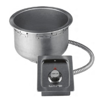
INSTALLATION INSTRUCTIONS
BUILT-IN ROUND FOOD WARMERS
MODELS SS-10ULT (TD, EUT, EUTD)
INCHES
(MM)
PRODUCT DIMENSIONS
4
(102)
6 1/4
(159)
2 3/4
(70)
IMPORTANT:
MOUNT APPLIANCE SO THAT THE CONTROL PANEL
IS LOCATED TO THE FRONT OF THE FIXTURE.
WARMER FLANGE
GASKET
WELLSLOK
SCREWDRIVER
COUNTERTOP
8 3/4
(222)
CONDUIT
1/2 NPT
(ULTD MODELS)
MASTER
CONTROL
PANEL
46221-3 REV (A)
Advertisement
Table of Contents


Need help?
Do you have a question about the SS-10EUT and is the answer not in the manual?
Questions and answers