Advertisement
Quick Links
Advertisement

Related Manuals for IFR COM-120B


Summary of Contents for IFR COM-120B
- Page 1 Rev. 1.0 Page 1...
- Page 2 Rev. 1.0 Page 2...
- Page 3 Thank you for taking the time to evaluate the IFR COM-120B. We know that your time is valuable, so we have included a demonstration kit complete with all of the accessories that you will need to evaluate the advanced features of the COM-120B.
- Page 4 ! Transmitter Distortion If you need assistance or have any questions about the COM-120B or performing any of the experiments in this guide, do not hesitate to call our toll free number: (800) 835-2352 and select menu item 1. You will be able to speak to a trained specialist who is well versed with this product.
- Page 5 The Antenna port is designed for low Off the Air level off-the-air signals but has input protection for up to 10 Watts in case of accidental connection to transmitter. Transmitter connection Full Duplex Testing Receiver Transmitter Half-Duplex Input testing Up to 50 Watts +13 dBm Continuos...
- Page 6 Scope / DVM Input AUDIO / DATA (200 VRMS Max) GEN OUT External Mod 0 – 1.7 VRMS source for radio AUDIO / DATA under test SINAD IN (15mV – 15V) DEMOD External Audio EXT MOD IN Analysis 2 kHz / Vpk Narrow 10 kHz / Vpk Wide Microphone Input...
-
Page 7: Master Power Switch
Master Power Switch Battery Ext. DC Compartment Input Replaceable 12-30 VDC Battery (Carry a Spare) RS-232 Serial I/O Optional 10 MHz Ext. Direct pin to pin GPIB Reference Input connection to PC Interface LID / Storage Unit AC Line Cord DC Line Cord Antenna Fuses... - Page 8 The COM-120B provides a powerful set of insturments to allow repair, calibration and diagnostic evaluations of communications systems. The COM-120B organizes test functions into screens that can be selected and altered to perform specific tests.
- Page 9 COM-120B’s Antenna Input located in the upper right corner of the instrument. 3. Connect the AC Line cord to the COM-120B’s rear panel receptical and apply power with the power switch located in the lower left corner of the instrument.
-
Page 10: Basic Operation And Navigation
Basic Operation and Navigation This guide will provide some basic operational knowledge to allow configuration of the COM-120B but you should consult the Operators Guide for more detailed information. Begin by selecting a test mode of operation. Press the [REC] key now to enable the Transmitter Test screen. - Page 11 With the cursor still on the INPUT field, notice that the F1 and F2 key labels offer quick entry of the available selections. Quick entry is available when there are only a few available options. Some Field labels allow selection by MENU as shown in the screen image to the right.
- Page 12 Meter functions allow for zooming as well. In the example to the right, the cursor is placed on the RF Power meter field label. This allows access to the zoom feature for the meter. Pressing the [F1] key will zoom in on the RF Power meter allowing additional features to be accessed.
- Page 13 Setting up the Demonstration Software To access the System Setup Software used in this document, a program must be activated from the COM-120B’s file system. To do this, follow the procedure below. SHOW 1. Press the key. List 2. Press the F3 key “STORED FILES” to access the file directory.
- Page 14 REC – Transmitter Test Screen Exploded view of the function screens that are available in the REC screen. Rev. 1.0 Page 14...
- Page 15 Interconnect: 1. Connect the supplied Transmitter RF Output to the COM-120B’s T/R Input. 2. Turn the radio to the ON position and set to Channel 2. 3. It is not necessary to connect any audio cables at this time. The following procedures will lead through the process of: ! Finding an unknown transmitter frequency.
- Page 16 The receive screen is selected and the COM-120B is monitoring the Power meter for the presence of RF Power. 6. Key the Transmitter and the COM-120B will switch screens to the stand alone spectrum analyzer to find the transmitter signal. Once the signal is found, the COM-120B will return to the Receive screen to allow evaluation of the transmitter.
- Page 17 TX Frequency Tuning Either the Scope or Spectrum Analyzer can be viewed by positioning the cursor to the SCOPE or ANALYZER field and selecting the desired display with the F2 key. TX Frequency can be tuned by positioning the cursor to the RF ERROR label and pressing the F1 key “ZOOM”...
- Page 18 Signal Find Feature The Signal find feature is a function of the Spectrum Analyzer. To view the Spectrum Analyzer press the ANLYZ key on the front panel. Positioning the cursor to the RF Frequency field allows configuration of the signal find features. The entire RF spectrum or a small piece of the RF spectrum can be searched.
- Page 19 Test Voice Deviation Setup: 1. This COM-120B has been pre-configured for common transmitter test setups. START 2. Press the key to access the COM-120B System Setup STOP Utility software. 3. The menu to the right will appear. 4. Select STEP 2 by positioning the cursor and pressing F1 Execute.
- Page 20 8. Position the cursor to the Scope Label by pressing [TAB] [1] [ENTER] on the COM-120B’s keypad. 9. Press the F1 key labeled “ZOOM” to expand the scope to a full sized scope. With the Transmitter keyed, press the function keys that are labeled “PK HOLD”...
- Page 21 Test TX Squelch (CTCSS) Setup: 1. This COM-120B has been pre-configured for common transmitter test setups. START 2. Press the key to access the COM-120B System Setup STOP Utility software. 3. The menu to the right will appear. 4. Select STEP 3 by positioning the cursor and pressing F1 Execute.
- Page 22 Test TX Squelch (DCS) Setup: 1. This COM-120B has been pre-configured for common transmitter test setups. START STOP 2. Press the key to access the COM-120B System Setup Utility software. 3. The menu to the right will appear. 4. Select STEP 3 by positioning the cursor and pressing F1 Execute.
- Page 23 [F1] Execute. 5. The COM-120B will configure itself for decoding Transmitter DTMF codes. Interconnect: 1. Connect the Transmitter RF Output to the COM-120B’s T/R Input. 2. Connect the COM-120B’s Audio/Data Gen Out to the Radio’s Microphone Input. Rev. 1.0...
- Page 24 3. The supplied transmitter does not have a DTMF keypad so the COM- 120B’s internal DTMF generator will be used to simulate pressing keys on a radio’s DTMF keypad. The COM-120B’s DTMF generator will externally modulate the transmitter and the COM-120B’s receiver and DTMF decoder will decode the transmitted DTMF tone codes.
- Page 25 F1 Execute. 5. The COM-120B will configure itself for testing Transmitter Distortion. Interconnect: 1. Connect the Transmitter RF Output to the COM-120B’s T/R Input. 2. Connect the COM-120B’s Audio/Data Gen Out to the Radio’s Microphone Input. Rev. 1.0...
- Page 26 Measuring TX Distortion: 1. With the radio configured to channel 2, key the radio and observe a 1 kHz tone on the Scope at a level of 3 kHz deviation on the Deviation Meter. The Internal function generator is used to externally modulate the transmitter for this test.
- Page 27 This concludes the Transmitter test section of this procedure. If you would like ot try it out with one of your own radios, you may do so at this time. Use the software for setups as you did with our demonstration radio.
- Page 28 GEN – Receiver Test Screen Exploded view of the function screens that are available in the GEN screen. The generate screen provides all of the features that are required to provide stimulus to a receiver to evaluate performance characteristics. The Audio Level meter can be configured to measure VRMS, dB or dBm.
- Page 29 GEN – Receiver Test Screen Modulation Sources The COM-120B can be simultaneously modulated by up to 6 modulation sources. AM and FM can be mixed. This area identifies what sources are turned on GEN1 indicates that FGEN 1 is turned...
- Page 30 2. Connect the radio’s Audio Output to the COM-120B’s SINAD Input. 3. With the radio configured to channel 2, adjust the radio’s volume control for a 2 Vrms indication on the COM-120B’s AF LEVEL meter as shown on the next page.
- Page 31 4. Position the cursor to the Level field. [TAB] [4] [ENTER] 5. Press the [ENTER] key to highlight the RF Level value and adjust with the Knob control to reduce the level until the COM-120B’s SINAD meter indicates approximately 12 dB. Note: The monitor button on the radio may need to be held down to defeat the radio’s...
- Page 32 The SINAD meter can be expanded to allow more control by positioning the cursor to the SINAD meter label [TAB] [1] [6] [ENTER] and pressing the F1 key “ZOOM” ENTER ZOOM " Ensure the C-MSG Filter is enabled " Enable SINAD Average to 10 for manual measurements or turn Averaging OFF...
- Page 33 DUPLEX Operation Mode Duplex Mode Simultaneous Generate and Receive operation for Full Duplex Any Offset between Generate and Receive frequencies in 2.5 kHz steps Rev. 1.0 Page 33...
- Page 34 The Duplex screen offers the ability to generate and receive at the same time. Additionally, the Generate and Receive frequencies may be set to any frequency within the limitation of either the Receiver or the Generator. The Receiver could be set to 10.7 MHz or 455 kHz while the Generator is set to 151.625 MHz allowing signal tracing through IF strips.
- Page 35 This concludes the Receiver test procedure. There are other tests that can be performed on the receiver but are beyond the scope of this guide at this time. Please turn the radio power to the OFF position now and return it to the evaluation kit.
- Page 36 Measuring Filters Interconnect: 1. Connect an RF cable to the COM-120B’s AUX RF Output. 2. Connect an RF cable to the COM-120B’s Antenna Input. 3. Using a BNC Barrel, connect the two RF cables together forming a loop with two cables from the AUX RF Output to the Antenna Input of the COM-120B.
- Page 37 After the reference level has been established we will connect the provided duplexer to evaluate the above mentioned measurements. Note: The COM-120B has been placed into a unique Split screen mode of operation for the comprehensive evaluation of this filter.
- Page 38 Alignment screws. To adjust, loosen the nut and then turn the screw 1. Connect the Duplexer Antenna port to the COM-120B’s AUX RF Output. 2. Connect the Duplexer 160 MHz port to the COM-120B’s Antenna port. 3. Connect a 50-ohm Termination to the remaining port.
- Page 39 Position the cursor to the Atten field and select 0 dB input attenuation by pressing the F2 key. The right side may now be evaluated for the reject band. This image indicates that the filter has a notch depth of 100 dB because started with...
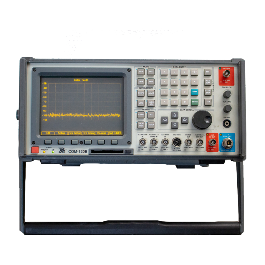
- Page 40 Measuring Cable Fault Setup: 1. This COM-120B has been pre-configured for common Analyzer test setups. START STOP 2. Press the key to access the COM-120B System Setup Utility software. 3. The menu to the right will appear. 4. Select STEP 9 by positioning the cursor and pressing F1 Execute.
- Page 41 1. Position the cursor to the Marker field label. 2. Press the F1 key to activate marker. 3. Press the ENTER key to edit the Marker Frequency. 4. Use the arrow keys to highlight the 1 MHz digit and then the Data Scroll knob to adjust the frequency value until the marker is placed directly on the minimum point of the first dip.
-
Page 42: Measuring Return Loss
LOAD Interconnect: 1. Connect the Return Loss Bridge as indicated in the graphic above. 2. Connect the Bridge Source Port to the COM-120B’s AUX RF Output. 3. Connect the Bridge Reflected Port to the COM-120B’s Antenna port. Setup: 1. This COM-120B has been pre-configured for common Analyzer test setups. - Page 43 3. The menu to the right will appear. 4. Select STEP 10 by positioning the cursor and pressing F1 Execute. 5. The COM-120B will configure itself for testing Return Loss. 6. Connect the Load port of the Return Loss bridge to the 160 MHz port of the Duplexer Filter.
- Page 44 This concludes the COM-120B Evaluation procedure. If you would like information or assistance with tests not covered by this procedure, please contact our technical staff for assistance at 1-800-835-2352 and select menu item 1. You will be able to speak to a trained specialist who is well versed with this product.
- Page 45 ! RF Signal Generator ! Output Level +13 to -130 ! 0.2 PPM TCXO ! 2 uV Receiver with 15, 30 and 300 kHz IF filters ! 50 kHz Scope ! Full band / Dual Mode Spectrum Analyzer ! Digital Voltmeter ! Audio Level Meter ! Dual Audio Function Generators ! Data Generator DCS, DCS INV...
- Page 46 ! 0.01 PPM OCXO (120B-xTx) ! Internal Rechargeable Battery (AC3001) ! Tracking Generator (AC3012) ! Return Loss Bridge (AC4105) ! EasySweep Software (AC1019) ! EasySpan for Windows (AC1009W) ! Digital / Analog Signaling (AC3011) ! CCIR, CCIRH, CCIRH4, EEA, ! EIA, NATEL, ZVEI, DZVEI, ! DDZVEI, EURO, 5/6 Tone, POCSAG ! RCC Signaling (AC3009)
Need help?
Do you have a question about the COM-120B and is the answer not in the manual?
Questions and answers