Table of Contents
Advertisement
Quick Links
Advertisement
Chapters
Table of Contents

Related Manuals for IFR 6970


Summary of Contents for IFR 6970
- Page 1 Artisan Technology Group is your source for quality new and certified-used/pre-owned equipment SERVICE CENTER REPAIRS WE BUY USED EQUIPMENT • FAST SHIPPING AND DELIVERY Experienced engineers and technicians on staff Sell your excess, underutilized, and idle used equipment at our full-service, in-house repair center We also offer credit for buy-backs and trade-ins •...
- Page 2 No part of this book may be reproduced or transmitted in any form or by any means, electronic or mechanical, including photocopying, or recorded by any information storage or retrieval system, without permission in writing by IFR Ltd. Printed in the UK Manual part no. 46882-182...
- Page 3 Typical uncertainty calculations ..............A-3 INTRODUCTION The 6970 uses the customary technique of power measurement of a sensor element at the power source with a remote signal processing unit. By using a microcontroller and digital signal processing techniques, sensor correction, calibration and zeroing factors can be used to give the best enhancement of measurement accuracy.
- Page 4 POWER MEASUREMENT ERROR ANALYSIS Power reference uncertainty When the power reference is used to calibrate the power meter and the power sensor together, the accuracy of the reference oscillator becomes part of the overall measurement uncertainty. Calculating measurement uncertainty For a source and load having complex reflection coefficients of Γ and Γ...
- Page 5 POWER MEASUREMENT ERROR ANALYSIS Typical uncertainty calculations Calculate the mismatch uncertainty for a source reflection coefficient of 0.33 and a sensor reflection coefficient of 0.05. Positive uncertainty = 100 × ((1 + 0.33 × 0.05) − 1) = 100 × ((1 + 0.0165) −...
- Page 6 CONTENTS PRECAUTIONS Chapter 1 GENERAL INFORMATION Chapter 2 INSTALLATION Chapter 3 OPERATION Chapter 4 TECHNICAL DESCRIPTION Chapter 5 ACCEPTANCE TESTING Appendix A POWER MEASUREMENT ERROR ANALYSIS INDEX 46882-182 Artisan Technology Group - Quality Instrumentation ... Guaranteed | (888) 88-SOURCE | www.artisantg.com...
- Page 7 PRECAUTIONS WARNINGS, CAUTIONS and NOTES These terms have specific meanings in this manual: WARNINGS contain information to prevent personal injury. CAUTIONS contain information to prevent damage to the equipment. contain important general information. Notes HAZARD SYMBOLS The meaning of hazard symbols appearing on the equipment is as follows: Symbol Nature of hazard Toxic hazard...
- Page 8 This equipment has been designed and manufactured by IFR Ltd. to for making power measurements in the range 0.1 nW to 25 W over a wide range of frequencies using the IFR 6900 series of power sensors.. IFR Ltd. has no control over the use of this equipment and cannot be held responsible for events arising from its use other than for its intended purpose.
- Page 9 PRECAUTIONS WARNINGS, CAUTIONS et NOTES Les termes suivants ont, dans ce manuel, des significations particulières: WARNINGS contient des informations pour éviter toute blessure au personnel. CAUTIONS contient des informations pour éviter les dommages aux équipements. Notes contient d’importantes informations d’ordre général. SYMBOLES SIGNALANT UN RISQUE La signification des symboles liés à...
- Page 10 WARNING - NICKEL CADMIUM Une batterie au cadmium nickel est utilisée dans cet équipement. Ne pas l'écraser ou la broyer, l'électrolyte contenu est corrosif. Ne pas l'incinérer cela risque de provoquer l'explosion et le dégagement de fumées toxiques. WARNING - ADAPTATEUR SECTEUR L’adaptateur secteur fourni avec l’appareil a été...
- Page 11 VORSICHTSMASSNAHMEN WARNINGS, CAUTIONS und NOTES Diese Hinweise haben eine bestimmte Bedeutung in diesem Handbuch: WARNINGS dienen zur Vermeidung von Verletzungsrisiken. CAUTIONS dienen dem Schutz der Geräte. Notes enthalten wichtige Informationen. GEFAHRENSYMBOLE Die Gefahrensymbole auf den Geräten sind wie folgt: Symbol Gefahrenart Warnung vor giftigen Substanzen Class II supply...
- Page 12 WARNING - NICKEL CADMIUM Eine Nickel-Cadmium-Batterie ist in diesem Gerät eingebaut. Das Gerät nicht beschädigen oder verbrennen, da ätzende Elektrolyte freigesetzt wird. Die Batterie kann dabei explodieren oder giftige Gase freisetzen. WARNING - NETZADAPTER Der mitgelieferte Netzadapter ist entsprechend der Norm BS EN 60950 (IEC 950) für die Sicherheit datentechnischer Anlagen, inklusive elektrischer Büromaschinen, ausgelegt und getestet worden.
- Page 13 PRECAUZIONI WARNINGS, CAUTIONS e NOTES Questi termini vengono utilizzati in questo manuale con significati specifici: WARNINGS riportano informazioni atte ad evitare possibili pericoli alla persona. CAUTIONS riportano informazioni per evitare possibili pericoli all’apparecchiatura. Notes riportano importanti informazioni di carattere generale. SIMBOLI DI PERICOLO Significato dei simboli di pericolo utilizzati nell’apparato: Simbolo...
- Page 14 WARNING - NICHEL CADMIO Quest ’apparato incorpora una batteria al nichel cadmio. Non tentare di rompere o comunque di manomettere la batteria in quanto essa contiene un elettroliti corrosivo. Non incenerire in quanto la batteria può esplodere o emettere dei fumi tossici.
- Page 15 PRECAUCIONES WARNINGS, CAUTIONS y NOTES Estos términos tienen significados específicos en este manual: WARNINGS contienen información referente a prevención de daños personales. CAUTIONS contienen información referente a prevención de daños en equipos. Notes contienen información general importante. SÍMBOLOS DE PELIGRO Los significados de los símbolos de peligro que aparecen en los equipos son los siguientes: Símbolo...
- Page 16 WARNING - NIQUEL CADMIO En este equipo se utiliza una batería de NiquelCadmio. No las aplaste o rompa ya que podría liberar electrólito corrosivo. No las queme ya que podría dar lugar a que la batería explote o libere humos tóxicos. WARNING - ADAPTADOR DE ALIMENTACIÓN A RED AC El adaptador de alimentación suministrado ha sido diseñado y probado según la normativa BS EN 60950 (IEC 950) “Seguridad en aparatos de tecnologías de la información, incluyendo...
-
Page 17: Table Of Contents
The unit can be used to measure RF and microwave power from -70 dBm (0.1 nW) to +44 dBm (25 W) over a wide range of frequencies using the IFR 6910, 6920 and 6930 series of power sensors. -
Page 18: Accuracy
ACCURACY High accuracy is achieved by applying calibration and linearity factor correction. All power sensors are supplied with individual calibration data. IFR 6900 series sensors all have an excellent return loss specification to minimise mismatch errors in power measurement. The integral calibrator provides a precision 0 dBm (1 mW) power reference at 50 MHz to give the same precision calibration standard as bench instruments. -
Page 19: Performance Data
Sensor calibration and linearity factors can be entered with the dual function keypad. The 6970 and power sensor can also be calibrated using the integral 0 dBm 50 MHz power reference with traceability to National Standards. - Page 20 Duty cycle Enables entry of duty cycle of pulsed signal in the range 0.01% to 100%. The 6970 calculates the peak value of the pulsed signal from the average power measured by the sensor. Audio limit Produces audible tones when the measured power is above or below programmed limits.
- Page 21 GENERAL INFORMATION Batteries 3, rechargeable Nickel-Cadmium AA size. Operating time >7 hours from full charge when new. Time to recharge <14 hours Power consumption 250 mW Battery charger 9 V to 21 V DC, 120 mA via a 2.1 mm power requirements connector.
-
Page 22: Options And Accessories
6900 Series Power Sensors SUPPORTED POWER SENSORS The 6970 supports the full range of IFR power sensors. 17 sensors are available, covering the frequency range from 30 kHz to 46 GHz (dependent upon sensor used). The power range depends on sensor type, and covers from -70 dBm (0.1 nW) to +44 dBm (25W). -
Page 23: Table 1-1 General Characteristics Of 6910, 6920 And 6930 Series Power Sensors
GENERAL INFORMATION TABLE 1-1 GENERAL CHARACTERISTICS OF 6910, 6920 AND 6930 SERIES POWER SENSORS WHEN USED WITH 6970 Sensor Frequency range Power range Connector 6910 10 MHz to 20 GHz -30 to +20 dBm N type (m) 6911 10 MHz to 20 GHz... - Page 24 Artisan Technology Group - Quality Instrumentation ... Guaranteed | (888) 88-SOURCE | www.artisantg.com...
- Page 25 GENERAL INFORMATION 46882-182 Artisan Technology Group - Quality Instrumentation ... Guaranteed | (888) 88-SOURCE | www.artisantg.com...
- Page 26 Different versions are available to suit different types of power socket. If there is a requirement to power or recharge the 6970 from a DC bench supply using the supplied DC power connector, the connector should be wired as shown in Fig. 2-1.
- Page 27 Any alternative AC Adapter should conform to the SELV requirements detailed in IEC950, EN60950, UL1950 (sec. 2.3) If the 6970 internal batteries have become almost completely discharged and a battery charger is connected, the instrument’s beeper will sound during the initial charging period (approximately one minute).
- Page 28 Chapter 3 OPERATION CONTENTS Page PANEL LAYOUT .....................3-2 KEYPAD ........................3-2 DISPLAY........................3-5 NOTE ON KEYPAD OPERATION AND LCD DISPLAYS........3-6 PREPARATION FOR USE..................3-6 KEY FUNCTIONS....................3-8 Zero........................3-8 Cal........................3-8 Units.......................3-9 Range ......................3-9 Lower limit ....................3-9 Upper limit.....................3-9 Peak indication....................3-10 Duty cycle correction ..................3-10 dB relative function ..................3-10 OTHER FUNCTIONS....................3-11 Averaging.......................3-11 Power-down stores..................3-11...
-
Page 29: Panel Layout
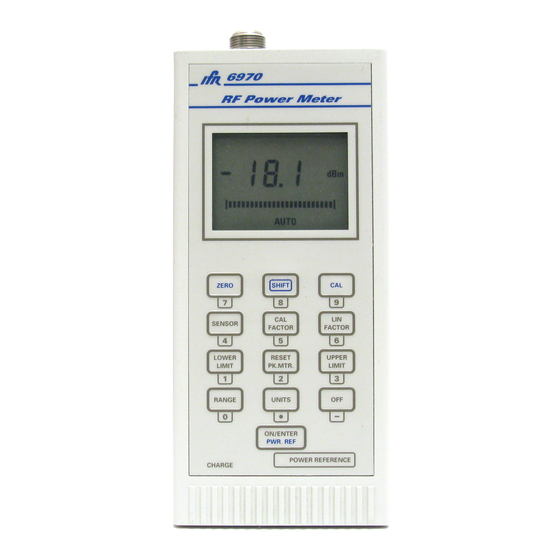
LOCAL OPERATION PANEL LAYOUT (Refer to Fig. 3-1.) Keypad. Dual function keys- see description below. Liquid crystal display. See Fig. 3-2. Power reference connector . SENSOR INPUT connector. Accepts multipin connector from supplied sensor input cable. DC input connector. 2.1 mm connector for 9 to 21 V DC supply for charging internal batteries. - Page 30 LOCAL OPERATION Fig. 3-1 6790 Power meter 46882-182 Artisan Technology Group - Quality Instrumentation ... Guaranteed | (888) 88-SOURCE | www.artisantg.com...
- Page 31 LOCAL OPERATION SENSOR (4) Allows the display and selection of the RF sensor type connected. The first press of the key will clear the display and display the current sensor type. Subsequent presses will step through the sequence of sensor type numbers. LIN FACTOR (5) For setting and examining sensor linearity factor.
-
Page 32: Display
LOCAL OPERATION LIN FACTOR CAL FACTOR µ W dBV mW dBm nW mV SENSOR AUTO MAN ZERO C0806 Fig. 3-2 Liquid crystal display DISPLAY The LCD comprises the following: NUMERICAL VALUE A three digit display of power reading (four if positive) in log format (dBm, dBV) and 4 digits in linear format (watts, volts), or the keypad entry value and the input amplifier range (r0, r1, r2, r3) when manually selecting ranges. -
Page 33: Note On Keypad Operation And Lcd Displays
Connect the AC adapter via the 2.1 mm connector at the bottom end of the instrument. An LED indicates charging in progress, and the 6970 will audibly "beep" whilst the batteries acquire sufficient charge to power-up the unit. For fully discharged cells, the beeper may sound for several minutes. - Page 34 For variants of sensor type, use the basic type number. Press [ON/ENTER] to confirm the selection. The default sensor is the IFR 6910. Enter the sensor’s LINEARITY FACTOR. This is shown on the sensor’s label or, more precisely (to two decimal places), on the Calibration Data Chart which accompanies the sensor.
-
Page 35: Key Functions
LOCAL OPERATION The 6970 is now ready to make uncorrected power measurements. Connect the sensor (via attenuator or matching unit as required) to the source to be measured. A power reading (in dBm) will be obtained. Note that a sensor zero and calibration will be required for accurate power measurements, as described in SUMMARY OF MEASUREMENT PROCEDURE page-3-12. -
Page 36: Units
LOCAL OPERATION Units The currently selected measurement units will be shown on the LCD. To change the units, press [UNITS]. If the current units are Watts, the instrument will select the appropriate scaling from W, mW, µW or nW; similarly with V or mV when Volts are selected. Available units are dB, dBm, W, V and dBV. -
Page 37: Peak Indication
When the 6970 is used to set up the output power level of a device under test, press [RESET PK. MTR.] to set the peaking indicator to half full scale. The range of the indicator is now ±5 dB about the input power level. -
Page 38: Other Functions
6970 employs an automatic restart averaging function which resets the averaging whenever an RF input level change is detected. If measurements are being made with modulated signals, manual range selection should be used to over-ride the automatic restart function. -
Page 39: Auto Power Off
Pressing [ON/ENTER] confirms the selection. SUMMARY OF MEASUREMENT PROCEDURE Preparation Select a sensor suitable for the measurement. Connect the sensor to 6970 using the supplied sensor cable. Turn on the unit by pressing [ON/ENTER]. Select the correct sensor type: step [SENSOR] [ENTER]. -
Page 40: Making Measurements
LOCAL OPERATION (12) Connect the sensor to the signal source to be measured and where feasible, with no RF power applied to the sensor, repeat the zero function: [SHIFT][ZERO]. Making measurements Select the appropriate measurement units by stepping the [UNITS] key. If required, select the appropriate range for the measurement by stepping the [RANGE] key to choose between MANual ranges r0, r1, r2, r3 or AUTOranging. -
Page 41: Sensor Overload Warning
LOW LEVEL POWER MEASUREMENTS The 6920 Power Sensor used with a 6970 Power Meter is an extremely sensitive measuring system capable of reading power levels as low as -70 dBm (-65 dBm for 6923/24 power sensors). It is therefore necessary to follow a few simple precautions to ensure an accurate reading at these low levels. - Page 42 (ADC), it also drives the liquid crystal display (LCD) and interfaces which the keypad. Program code is contained in internal ROM. The 6970 uses a signal chopper to provide a pulsed DC voltage which is proportional to the incident RF power and thus allows AC coupled differential amplification. The tuned input amplifier is distributed between the selected sensor and the 6970 input amplifier, as shown in Fig.
- Page 43 TECHNICAL DESCRIPTION The second stage amplifier scales the signal as appropriate over four ranges before feeding the ADC, which converts the analogue signal to a digital form suitable for the microcontroller to process and apply corrections. A digital/analogue converter (DAC) is used as part of the sensor zero operation to minimize and account for system offsets when no RF signal is applied.
- Page 44 TECHNICAL DESCRIPTION Fig. 4-1 6970 block diagram 46882-182 Artisan Technology Group - Quality Instrumentation ... Guaranteed | (888) 88-SOURCE | www.artisantg.com...
- Page 45 Power sensor IFR* 6900 series IFR* 6910 * IFR Ltd was previously known as Marconi Instruments Ltd With the internal batteries fully charged or with the external AC adapter connected, the following acceptance tests should be performed: Keypad test. Press and hold down the [SHIFT] key, press the [ON/ENTER] key, and then release the [ON/ENTER] key.
- Page 46 ACCEPTANCE TESTING power is incident on the sensor, then press [SHIFT][ZERO] to initiate a sensor zero: the peaking indicator shows time to completion. The warning message FAIL will be displayed on the LCD if the sensor fails to zero correctly. Sensor Calibration Connect a 6910, 6920 or 6930 series sensor to the internal 50 MHz power reference (if fitted) or an external 50 MHz 0 dBm standard.
- Page 47 ACCEPTANCE TESTING Note... If the or indication does not apper on range 1 even when the maximum output level of the signal generator has been reached then this level (+13 dBm) should be used for the measurement. Press [ON/ENTER] to restart averaging and wait 5 seconds. Press [SHIFT][OFF] to reset dB Rel, then press [ON/ENTER].
- Page 48 For maximum accuracy it is important to allow sufficient warm-up time for the equipment used in this test. For the EPM-1 one hour should be allowed. Calibrate the milliwatt power meter then connect the probe to the 6970 POWER REFERENCE output.
- Page 49 Index AC adapter ........1-3, 2-1 Options and accessories......1-7 Acceptance testing ........5-1 Accuracy ...........1-2 Auto power off........3-12 Peak indication ........3-10 Averaging ..........3-11 Performance data ........1-3 restart ........3-2, 3-11 Power measurement error analysis . App. A-1 Power reference .........1-2, 3-8 Power requirements ........2-1 Battery charging......
- Page 50 Artisan Technology Group is your source for quality new and certified-used/pre-owned equipment SERVICE CENTER REPAIRS WE BUY USED EQUIPMENT • FAST SHIPPING AND DELIVERY Experienced engineers and technicians on staff Sell your excess, underutilized, and idle used equipment at our full-service, in-house repair center We also offer credit for buy-backs and trade-ins •...
Need help?
Do you have a question about the 6970 and is the answer not in the manual?
Questions and answers