
Related Manuals for Best-Rite 795 Modifier XV


Summary of Contents for Best-Rite 795 Modifier XV
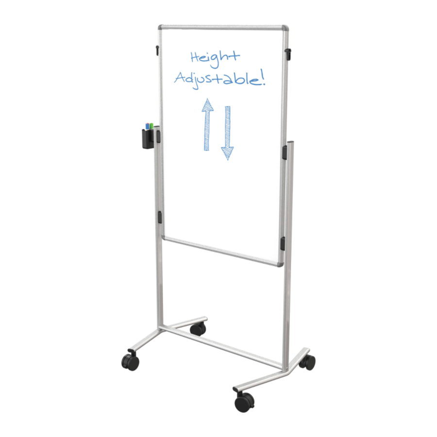
- Page 1 Best-Rite Modifier XV Adjustable Height Easel - 2 Sided Melamine Whiteboard (Black Frame) Instruction Manual...
- Page 2 1 2 3 4 5 6 7 8 9 0 1 2 3 4 5 6 7 8 9 0 1 2 3 4 5 6 7 8 9 0 1 2 1 2 3 4 5 6 7 8 9 0 1 2 3 4 5 6 7 8 9 0 1 2 3 4 5 6 7 8 9 0 1 2 1 2 3 4 5 6 7 8 9 0 1 2 3 4 #795 Modifier XV...
- Page 3 #795 Modifier XV Part Drawing Description Part Drawing Description Hardware List Welded Leg 2 EA Screw M6x38mm 2 EA Phillips Screw Short 5 EA Phillips Screw Long 5 EA Markerboard Panel 1 EA 2” Locking Caster 2 EA 2” Non-Locking Caster...
- Page 4 Insert 4 StorageTubs (P6). BEFORE HROUGH NSTRUCTIONS FROM BEGINNING TO END STARTING TO ASSEMBLE UNIT To Assemble: Identify and Separate all the Parts and Hardware. Attach 2 Locking Casters (C) and 2 Non-Locking Casters (C1) to the Bottom of the 2 Legs (P-1) Tighten casters using Caster Wrench (E).
- Page 5 4.) Attach five Plastic Receivers (F) to the Legs (P1) using one Phillips Screw Short (B) at the top and one Phillips Screw Long (B1) at the bottom of each as shown in illustration #3. Illustration # 3 Hook the Marker Board Panel (P2) into the Plastic Receivers (F) at the height you want. Hook the Plastic Cup (G) into the Plastic Receiver (F) on the outside of the Leg (P1) as shown in illustration #4.
- Page 6 #795 Modifier XV 795_7-01-14 WWW.MYBINDING.COM...
Need help?
Do you have a question about the 795 Modifier XV and is the answer not in the manual?
Questions and answers