
Related Manuals for Best-Rite Euro Reversible 667RU


Summary of Contents for Best-Rite Euro Reversible 667RU
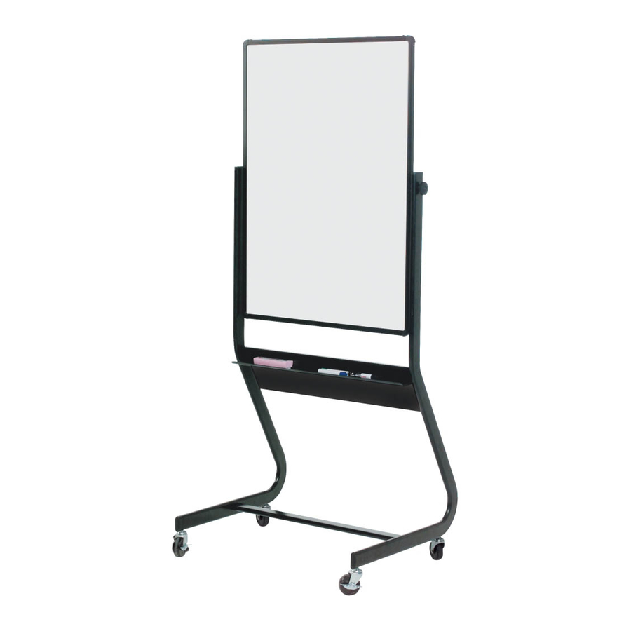
- Page 1 Best-Rite 40" x 30" Euro Mobile Reversible 2-Sided Dura-Rite Whiteboard with Black Frame Instruction Manual...
- Page 2 1 2 3 4 5 6 7 8 9 0 1 2 3 4 5 6 7 8 9 0 1 2 3 4 5 6 7 8 9 0 1 2 1 2 3 4 5 6 7 8 9 0 1 2 3 4 5 6 7 8 9 0 1 2 3 4 5 6 7 8 9 0 1 2 1 2 3 4 5 6 7 8 9 0 1 2 3 4 1 2 3 4 5 6 7 8 9 0 1 2 3 4 5 6 7 8 9 0 1 2 3 4 5 6 7 8 9 0 1 2 1 2 3 4 5 6 7 8 9 0 1 2 3 4 5 6 7 8 9 0 1 2 3 4 5 6 7 8 9 0 1 2 1 2 3 4 5 6 7 8 9 0 1 2 3 4 1 2 3 4 5 6 7 8 9 0 1 2 3 4 5 6 7 8 9 0 1 2 3 4 5 6 7 8 9 0 1 2 1 2 3 4 5 6 7 8 9 0 1 2 3 4 5 6 7 8 9 0 1 2 3 4 5 6 7 8 9 0 1 2 1 2 3 4 5 6 7 8 9 0 1 2 3 4 1 2 3 4 5 6 7 8 9 0 1 2 3 4 5 6 7 8 9 0 1 2 3 4 5 6 7 8 9 0 1 2 1 2 3 4 5 6 7 8 9 0 1 2 3 4 5 6 7 8 9 0 1 2 3 4 5 6 7 8 9 0 1 2 1 2 3 4 5 6 7 8 9 0 1 2 3 4...
- Page 3 Euro Reversible Part Drawing Description Part Drawing Description Hardware List Socket Screw 6*12mm 8 EA Right Leg 1 EA Caster Lock Washer 4 EA Flange 2 EA Knob 2 EA 4” Locking Caster 4 EA Allen Wrench 1 EA Left Leg 1 EA Caster Wrench 1 EA...
-
Page 4: Assembly Diagram
Euro Reversible Assembly Diagram HROUGH NSTRUCTIONS FROM BEGINNING BEFORE TO END STARTING TO ASSEMBLE UNIT To Assemble: Identify and Separate all the Parts and Hardware. 2. Install Cross bar (P-4) to the Legs (P-1) and (P-2) by using Socket Screws (A). Tighten with Allen Wrench (F). - Page 5 Illustration # 3 Detach 2 screws from each side of Framed Board (P-5) with Phillips Screwdriver as shown in illustration # 3. Screw Screw Screw Install Flange (C) on each side of the board by using the same 4 screws from step 5 and tighten with Phillips Screw- Screw driver.
- Page 6 Euro Reversible Illustration # 5 6. Separate the Legs (P-1) and (P-2) slightly in order to insert the flange bolts through the flanges on legs. Fasten the Knobs (D) to secure the board in place. See illustration # 5. 7. Assemble Tray (P-3) to the legs with using Socket Screws (A) and tighten with Allen Wrench (F).
- Page 7 Euro Reversible 667 36” 78” 78” 81” 25” 33” 75” 30 1/2”...